The Major head losses (pressure drop in pipes) are the energy losses due to friction of the fluid in a conduit of constant section. they are expressed in fluid heights (meters) and pascals.
DH is the pressure drop in fluid meter column
l is the major head losses corefficient

V is average velocity of the flow
D is diameter of the pipe flow
L is the lenth of the pipe flow
SOFTWARE HEAD LOSS CALCULATION:
procedure for calculating major head losses, aeraulic or hydraulic with Mecaflux software:
The software calculates the loss of regular load, but some information must be provided in the "entry area parameters"
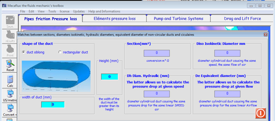
Enter pipe diameter (or equivalent diameter if the section is not round) in mm The section of the duct can bee circular , rectangular or oblong, a window calculation equivalent diameter is integrated in setting of the pipe. 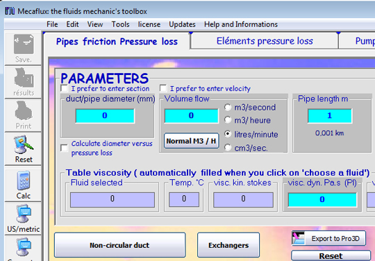
- Enter the flow rate in the selected unit .if the choice of units proposed is not enough, you can use the converter integrated into mecaflux
- Enter the length of the pipe in meters.
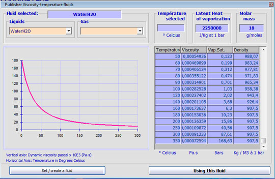
- Choose fluid from fluid editor
in the viscosity chart you select a fluid at a desired temperature, the dynamic viscosity is given. (you can create, save, or edit fluids in the database of the editor fluids)
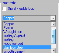
- choose the material of the pipe and its roughness is automatically given (the editor roughness offers + 140 roughness data can cover all cases encountered in study of air or water supply)
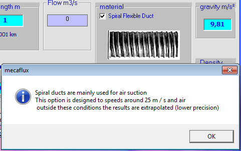
You can also opt for a spiral sheath:
Press "compute pressure loss to see major head losses. (If a required parameter is missing a message" insufficient parameters will warn you)
pendant le calcul:
1. il peut vous être proposé de choisir entre deux équations, les résultats s'en ressentent peu, mais vous pouvez ainsi comparer des méthodes de calculs différentes.
2. il peut vous être proposé de choisir entre deux régimes d'écoulement quand vous êteDuring the calculation:
- You may be offered a choice of two equations, the results are similar, but you can compare different methods of calculation.
- You may be offered a choice between two flow regimes when you are close to the limits of transition between laminar and turbulent flow.. This transition is often brought into reality by defects in roughness. (if you restart the calculation by slightly modifying the roughness you switch to a regime or another)
- the pressure drops are given in fluid heights (in meters) and pascals.
- the section of the conduit in m²
- the average fluid velocity in ms
- the maximum flow velocity in ms
- the coefficient of head loss (dimensionless coefficient )
- flow type
- Equation used
- Reynolds number
And use them for the calculation of pump or turbine power: the computed pressure drop is directly inserted into the tab and pump turbines

Mecaflux therefore uses an ergonomic and user-friendly interface as well as a spreadsheet to edit the results as, inventory losses in the network.
