Page contents
What is aerodynamics?
Aerodynamics is the branch of fluid mechanics that studies the forces exerted by air in relative motion on a body: aircraft, wing, propeller, vehicle, building. These forces split into drag, along the flow, and lift, perpendicular to it. Both are proportional to the density of air, to a reference area and to the square of the velocity, the rest being contained in two dimensionless coefficients, Cx (Cd) and Cz (Cl), measured in a wind tunnel or computed, which depend on the shape, the angle of attack and the Reynolds number.
Drag and lift formulas
- Fx, Fz: drag and lift, in newtons
- ρ: density of air, 1.225 kg/m³ at sea level and 15 °C
- S: reference area, in m²: frontal area for a body, wing area for a wing
- V: relative speed of the air with respect to the body, in m/s (1 km/h = 0.278 m/s)
- Cx, Cz: drag and lift coefficients (Cd, Cl), dimensionless, functions of the shape, the angle of attack and the Reynolds number (polar curve)
- L: reference length (wing chord), in m; ν: kinematic viscosity of air, 1.5 × 10⁻⁵ m²/s
Drag coefficients of common shapes
| Shape | Cx | Note |
|---|---|---|
| Flat plate perpendicular to the wind | 1.1 to 1.3 | Depends on the aspect ratio |
| Hollow half-sphere facing the wind (parachute) | 1.3 to 1.4 | 0.4 the other way round |
| Long cylinder, axis perpendicular | 1.0 to 1.2 | Drops to 0.3 beyond Re ≈ 3 × 10⁵ |
| Sphere | 0.45 to 0.5 | Drops to 0.1 to 0.2 beyond Re ≈ 3 × 10⁵ (drag crisis) |
| Cube facing the wind | 1.05 | |
| Streamlined body (teardrop, spindle) | 0.04 to 0.1 | Ten times less than a sphere of the same frontal area |
| Modern car | 0.25 to 0.35 | S ≈ 2 to 2.5 m²; S·Cx ≈ 0.6 to 0.8 m² |
| Cyclist | 0.9 to 1.1 | S ≈ 0.4 to 0.6 m² depending on the position |
Detailed explanations and calculation in Mecaflux
We will see in this lesson a few aerodynamic concepts.
Other links further information: the propeller fan and blower , the calculation of propeller, and software propeller calculation
When an object is immersed in a fluid stream, there is phenomena of friction and turbulence.
-
when the fluid is air, the study of these phenomena is the aerodynamics.
-
when the fluid is water, the study of these phenomena is the Hydrodynamics .
In the air , effects of friction are studied experimentally in wind tunnel.
it is in a wind tunnel that Cd ( aerodynamics coefficient of drag) and CL (coefficient lift ) Is studied according to the Aifoils or hydrofoils .
These results are often represented as Polar

concord testing

wind tunnel eiffel
(the engineer who created the tower devoted the rest of his life in aeronautics research)

NASA wind tunnel
From these experiments are derived information linking fluid characteristics and tested object.- The fluid characteristics are its viscosity , speed , And density
- characteristics of the object are its width, length, form, roughness, angle of incidence, its frontal area
- Cd (drag force coefficient) p is the density fluid Kg/m3 The S front surface m² v the relative velocity of the fluid * m / s
-
Drag= CD* p * s * (v²/2) become : Cx= Traînée/(p* s * (v²/2))
Drag in Newtons
- Cl (Lift force coefficient)
The Cz is the coefficient of lift, it is determined experimentally in wind tunnels or basin
p is the fluid density Kg/m3
S the projected surface ground m²
v the relative velocity of the fluid m / s
- Lift force=Cl * p * s * (v²/2) Become : Cl= Lift force/(p x s x (v²/2))
Calculation of drag and lift, of an airship hull, submarine or boat with the software HELICIEL
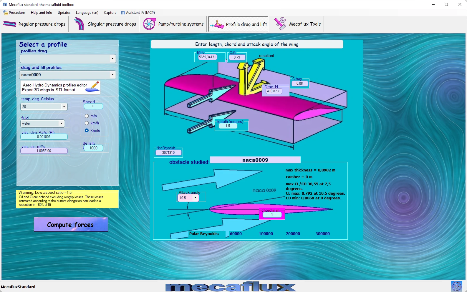
mecaflux is a simplified software, calculation of wing or sail.
HELICIEL is a software wing propeller calculation sail more complete.
Frequently asked questions
How do I calculate the wind force on a surface?
F = ½ ρ S V² Cx. For a 1 m² plate facing a 100 km/h wind (27.8 m/s) with Cx = 1.2: F = 0.5 × 1.225 × 1 × 27.8² × 1.2 = 568 N, the weight of 58 kg. The dynamic pressure alone, ½ ρ V², is 473 Pa.
Why does drag increase with the square of the speed?
Because the force is proportional to the dynamic pressure ½ ρ V². Doubling the speed quadruples the drag, and since the power required is F × V, it is multiplied by eight: this is why a vehicle's fuel consumption soars at high speed.
What is the difference between Cx and Cz?
Cx (Cd) measures drag, the force opposing motion; Cz (Cl) measures lift, the force perpendicular to the relative wind that supports a wing or presses a car onto the road. Their ratio Cz/Cx is the lift-to-drag ratio: 15 to 20 for an airliner wing, 40 to 60 for a glider.
How do I calculate the lift and drag of my own wing, vehicle or propeller?
Mecaflux Standard computes the drag of geometric shapes and plates, the lift and drag of wings and fins from aerofoil polars, and skin friction; Heliciel designs propellers, wings and wind turbines with blade element theory. For a drone, a vehicle, a wind turbine or a structure exposed to wind, Mecaflux carries out the study of your project, or offers training on the software applied to your own project.