Page contents
What is the chord of an aerofoil and what is it used for in calculations?
The chord c of an aerofoil is the segment joining the leading edge to the trailing edge: it is the width of the wing, blade or fin. Every quantity of the aerofoil is referred to it: the relative thickness t/c, the relative camber f/c (maximum distance between the chord and the mean line), the position of maximum thickness, and the angle of attack is the angle between the chord and the relative wind. The chord also sets the wing area S = c × span and the Reynolds number Re = V c / ν on which the polars depend. Example: a NACA 2412 with a 1 m chord has a maximum thickness of 120 mm and a camber of 20 mm, located 400 mm from the leading edge.
Formulas linked to the chord
- c: chord, in m; tmax: maximum thickness of the aerofoil, in m; f: maximum camber of the mean line, in m
- b: span (length of the wing or blade), in m; S: area of a rectangular wing, in m²
- λ: aspect ratio, dimensionless (b²/S for a non-rectangular wing)
- Re: Reynolds number of the aerofoil; V: relative speed, in m/s; ν: kinematic viscosity of the fluid, in m²/s
Reading the NACA designation for a 1 m chord
| Aerofoil | Maximum camber | Camber position | Maximum thickness | Typical use |
|---|---|---|---|---|
| NACA 0009 | 0 (symmetrical) | — | 9 % → 90 mm | fins, rudders, tailplanes |
| NACA 0012 | 0 (symmetrical) | — | 12 % → 120 mm | keels, helicopter blades |
| NACA 2412 | 2 % → 20 mm | 40 % → 400 mm | 12 % → 120 mm | light aircraft wings |
| NACA 4412 | 4 % → 40 mm | 40 % → 400 mm | 12 % → 120 mm | high-lift wings, blades |
| NACA 6409 | 6 % → 60 mm | 40 % → 400 mm | 9 % → 90 mm | models, slow flight |
| Clark Y | ≈ 3.4 % → 34 mm | ≈ 42 % → 420 mm | 11.7 % → 117 mm | propellers, light aviation |
Reynolds number against chord and speed
| Case | Chord c | Speed V | Reynolds number |
|---|---|---|---|
| Yacht keel at 6 knots (water) | 1 m | 3.09 m/s | 3.1 × 10⁶ |
| Windsurf fin at 6 knots (water) | 0.3 m | 3.09 m/s | 9.2 × 10⁵ |
| Light aircraft wing at 30 knots (air) | 2 m | 15.4 m/s | 2.0 × 10⁶ |
| Model aircraft wing at 30 knots (air) | 0.5 m | 15.4 m/s | 5.1 × 10⁵ |
| Drone propeller at 15 m/s (air) | 0.15 m | 15 m/s | 1.5 × 10⁵ |
| Wind turbine blade at 60 m/s (air) | 1 m | 60 m/s | 4.0 × 10⁶ |
Detailed explanations and calculation in Mecaflux
The chord of an aerodynamic or hydrodynamic profile is the dimension between the leading edge and the trailing edge of a profileit is the width of the wing:
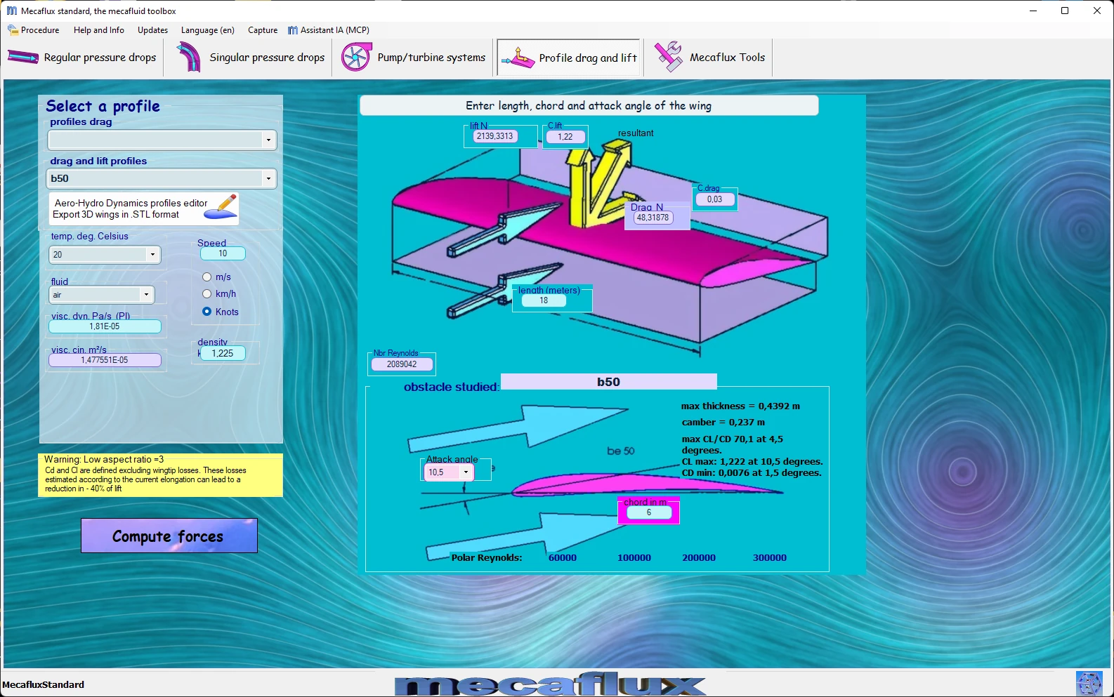
when you enter the aerofoil chord, its maximum thickness and camber are updated immediately
maximum thickness / chord = relative thickness
camber or arrow = maximum distance between the rope and the center line profile

- The lift but also drag,of a profile increases with its camber and thickness
- The thin profile and low camber, have a better lift / drag ratio but less strength...
for more information: the chord of aerodynamic and hydrodynamic profiles
Frequently asked questions
What is the difference between camber and thickness of an aerofoil?
Thickness is the distance between upper and lower surfaces, measured perpendicular to the chord: it gives structural strength and delays the stall, but increases drag. Camber is the curvature of the mean line: it creates lift from zero incidence and raises the maximum CL, at the cost of a nose-down pitching moment and higher drag at low lift. A symmetrical aerofoil has zero camber.
How does the chord enter the Reynolds number?
The Reynolds number of an aerofoil is computed with the chord as the reference length: Re = V c / ν. Wind tunnel polars are given for a specific Re; a small chord (drone, model aircraft) works near Re = 10⁵, where the maximum CL is lower and the drag higher than at Re = 10⁶, with laminar separation bubbles. The polar must therefore be chosen at the right Reynolds number.
Which chord should I take for a tapered wing?
The geometric mean chord is S / b, area divided by span. For moment calculations the mean aerodynamic chord is used: for a trapezoid of taper ratio λt = ctip / croot, it equals (2/3) croot (1 + λt + λt²) / (1 + λt). A wing of 2 m at the root and 1 m at the tip has a mean chord of 1.5 m and a mean aerodynamic chord of 1.56 m.
How do I choose the chord and aerofoil of my own wing or fin?
In Mecaflux Standard, as soon as you enter the chord, the thickness and camber of the chosen aerofoil are displayed, and the drag and lift tab computes lift and drag for the chord, span, speed and angle of attack of your project; the aerofoil editor lets you create your own from its coordinates and polars, then export it to CAD. Heliciel defines the chord distribution along the span (elliptical, trapezoidal or free law) with the twist and exports the wing or blade in 3D. For a wing, a fin or a blade to draw, Mecaflux carries out the study of your project, or offers training on the software applied to your own project.