Page contents
How do I read a NACA aerofoil designation and plot its shape?
An aerofoil (or hydrofoil section) is the cross-section of a wing, a blade or a keel; its shape sets its lift, its drag and its structural strength. 4-digit NACA aerofoils can be read directly: for a NACA MPXX, M is the maximum camber in per cent of the chord, P its position in tenths of chord and XX the relative thickness in per cent. A NACA 2412 therefore has 2 % camber located at 40 % of the chord and 12 % thickness; a NACA 0012 is symmetrical (M = 0) and 12 % thick. The half-thickness yt is calculated at every point with the NACA polynomial, the maximum thickness lies at 30 % of the chord and the leading-edge radius equals 1.1019 × t² (1.6 % of the chord for 12 % thickness). The generator below plots a 4- or 5-digit NACA aerofoil, gives its thickness, camber, leading-edge radius and zero-lift angle, and exports its coordinates for Heliciel or a CAD program.
4-digit NACA aerofoil formulas
- x: position along the chord, referred to the chord (0 at the leading edge, 1 at the trailing edge); all ordinates are fractions of the chord
- yt: half-thickness of the section; t: relative thickness (XX/100); the last coefficient is −0.1036 to close the trailing edge
- yc: ordinate of the mean line (camber line); m: maximum camber (M/100); p: camber position (P/10); upper and lower surfaces are obtained by laying off ± yt perpendicular to the mean line
- rLE: leading-edge radius; α₀: zero-lift angle, negative for a cambered section (thin aerofoil theory: −2.1° for 2 % camber at 40 %)
Half-thickness of the NACA 0012 aerofoil along the chord
| x / chord | 0 % | 1.25 % | 2.5 % | 5 % | 10 % | 20 % | 30 % | 40 % | 50 % | 60 % | 70 % | 80 % | 90 % | 100 % |
|---|---|---|---|---|---|---|---|---|---|---|---|---|---|---|
| yt | 0 | 1.89 % | 2.61 % | 3.55 % | 4.68 % | 5.74 % | 6.00 % | 5.80 % | 5.29 % | 4.56 % | 3.66 % | 2.62 % | 1.45 % | 0.13 % |
Some common NACA aerofoils and how to read them
| Aerofoil | Thickness | Camber | Camber position | α₀ | Typical use |
|---|---|---|---|---|---|
| NACA 0012 | 12 % | 0 (symmetrical) | 0° | tailplanes, fins, rudders, propeller blades | |
| NACA 0015 | 15 % | 0 (symmetrical) | 0° | keels, rudders, thick blades | |
| NACA 2412 | 12 % | 2 % | 40 % | −2.1° | light aircraft, general-purpose wings |
| NACA 4412 | 12 % | 4 % | 40 % | −4.2° | slow high-lift wings, wind turbine blades |
| NACA 4415 | 15 % | 4 % | 40 % | −4.2° | older gliders, wind turbine blade roots |
| NACA 6409 | 9 % | 6 % | 40 % | −6.2° | model aircraft, low Reynolds numbers |
| NACA 23012 (5 digits) | 12 % | 1.8 % | 15 % | ≈ −1.2° | aircraft, propellers: forward camber, low pitching moment |
Detailed explanations and calculation in Mecaflux
Note about profiles: Methods for aerodynamic testing also apply to the water test.. However, two principles related to liquids must be understood: cavitation and ventilation..
The airfoils are forms studied in wind tunnels. Wind tunnel tests, measure the profile's lift and drag. parameters of the experiment are stored in databases.
When it is desired to design a wing, a sail, a daggerboard or any other object whose lift and drag is important to us, it is useful to refer to the database to select an existing profile, which combined the qualities we are looking for, before reinventing the wheel.
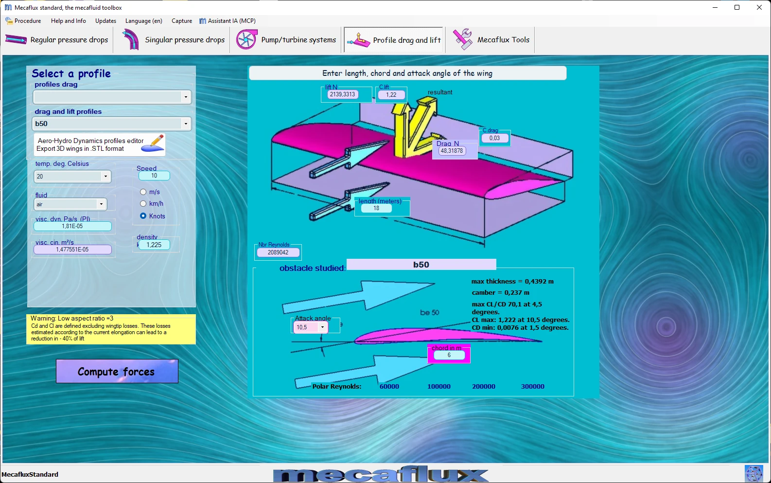
(maximum thickness) / chord = relative thickness
Camber = maximum distance between the rope and the center line profile:

- The lift, but also a profile drag, increases with its camber and thickness
- Thin and low camber profiles have a better lift/drag ratio, but less mechanical resistance.
A method of geometric construction profiles according to a mathematical equation been developed by the NACA.
The famous NACA profiles are built from the DIGITS of their name. Mecaflux integrated editor NACA 4 DIGITS profiles that allows you to very simply create a coordinate file and profile drawing by varying DIGITS profile with a cursor:
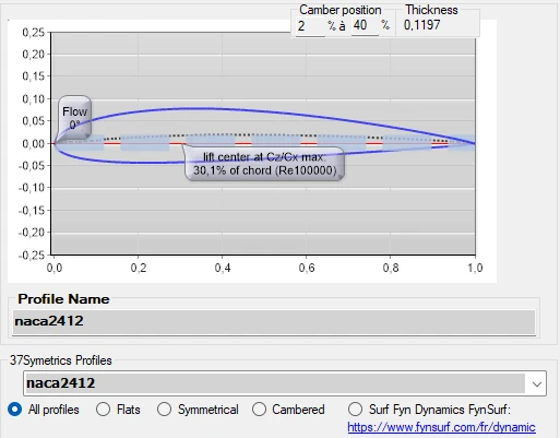
- You can also use a list of files coordinate Profile: Download List profile coordinate ZIP
- vous pouvez utiliser un profils déjà intégré à MECAFLUX standard (vous n'aurez qu'à choisir votre profil)
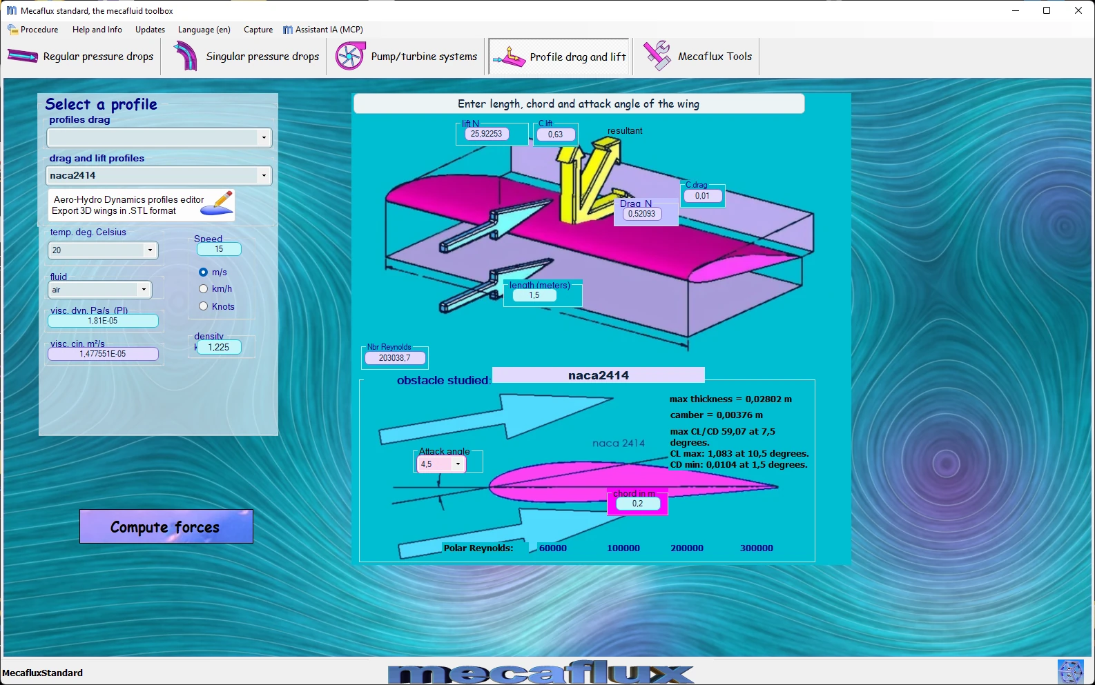
Calculations of lift and drag of AERODYNAMIC OR HYDRODYNAMIC profiles with Mecaflux Standard:
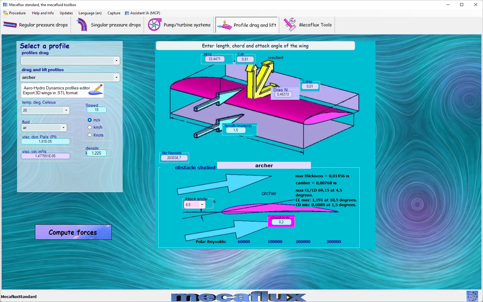
Set speed, fluid, incidence, length and chord, of the wing or daggerboard profile, to get the produced lift and drag .
-
Or you can create your profile by your own tables coordinate with the integrated profile editor mecaflux to export your files to solidworks and create a wing 3D file :

A more detailed report on the aerodynamic and hydrodynamic profiles is available at Heliciel
Frequently asked questions
What is the difference between a 4-digit and a 5-digit NACA aerofoil?
Both families share the same thickness law; they differ by the mean line. In the 4-digit series the camber is a parabola placed between 20 and 60 % of the chord. In the 5-digit series (23012, 23015…), the first digit times 1.5 gives the design lift coefficient in tenths (2 → 0.3), the next two divided by two give the position of maximum camber in per cent of chord (30 → 15 %) and the last two the thickness. The very forward camber gives a good maximum CL with a low pitching moment, hence their use on light aircraft and propellers.
How do I choose the thickness and camber of an aerofoil?
Thickness brings structural strength and a gentle stall, but increases drag: 12 to 18 % for a wing or a blade root, 6 to 9 % at a blade tip and for high speeds. Camber raises the lift at a given angle of attack and shifts the best lift-to-drag ratio towards high CL: high to fly or turn slowly, low or zero when the section must work both ways (keel, rudder, tailplane). The Reynolds number matters too: at the low Reynolds numbers of drones and models, thin cambered sections win. In water, a thick section with a rounded leading edge delays cavitation.
What is the zero-lift angle and what is it used for?
It is the angle of attack α₀ at which a cambered section no longer lifts; it is negative, about −1° per per cent of camber for 4-digit sections. It allows the lift to be estimated below the stall with CL ≈ 0.11 × (α − α₀) per degree: a NACA 2412 at 4° of incidence lifts like a symmetrical section at 6.1°, i.e. CL ≈ 0.67. It is also used to set the pitch of propeller blades or the rigging angle of a wing relative to the fuselage.
How do I get the lift of my own aerofoil and apply it to my wing or propeller?
Mecaflux Standard calculates the lift and drag of 11 built-in aerofoils, and its aerofoil editor plots your 4-digit NACA sections, computes their polar with Xfoil and exports the coordinates to SolidWorks to model the wing in 3D. Heliciel goes further with a database of hundreds of aerofoils and their polars over a wide Reynolds range, applied element by element to a wing, a foil or a propeller. For a wing, blade or keel project, Mecaflux carries out the study of your project and delivers the calculation report, or offers training on the software applied to your own case.