Page contents
How do I calculate the velocity of a fluid with the continuity equation?
The continuity equation expresses the conservation of mass: in steady flow, the mass flow entering a pipe section leaves it entirely. For an incompressible fluid (liquids, air at low speed), the volume flow rate Q = S × V is the same at every point: where the section decreases, the average velocity increases in the same ratio, and vice versa. The velocity at B follows from that at A by VB = VA × SA/SB, i.e. VA × (DA/DB)² for circular pipes: halving the diameter multiplies the velocity by four. Example: 10 m³/h of water flows at 1.25 m/s in a DN 50 pipe (53.1 mm bore) and at 4.75 m/s in a DN 25 (27.3 mm). For a gas being compressed or expanded, it is the mass flow ρ S V that is conserved.
Continuity equation formulas
- Q: volume flow rate, in m³/s (1 m³/h = 1/3,600 m³/s), constant for an incompressible fluid
- S: flow area, in m²; for a circular pipe S = π D²/4, D being the bore in m
- V: average velocity of the fluid in the section, in m/s
- ρ: density, in kg/m³, constant for a liquid, variable for a gas being compressed or heated
- qm: mass flow rate, in kg/s, always conserved
Velocity of 10 m³/h of water against pipe diameter
| Pipe | Bore | Area S | Velocity V |
|---|---|---|---|
| DN 25 | 27.3 mm | 5.85 cm² | 4.75 m/s |
| DN 32 | 36.0 mm | 10.2 cm² | 2.73 m/s |
| DN 40 | 41.9 mm | 13.8 cm² | 2.01 m/s |
| DN 50 | 53.1 mm | 22.1 cm² | 1.25 m/s |
| DN 65 | 68.9 mm | 37.3 cm² | 0.75 m/s |
| DN 80 | 80.9 mm | 51.4 cm² | 0.54 m/s |
| DN 100 | 105.3 mm | 87.1 cm² | 0.32 m/s |
Effect of a contraction on velocity
| Diameter ratio D₁ / D₂ | Area ratio S₁ / S₂ | Downstream velocity V₂ for V₁ = 1 m/s |
|---|---|---|
| 1.25 | 1.56 | 1.56 m/s |
| 1.5 | 2.25 | 2.25 m/s |
| 2 | 4 | 4.0 m/s |
| 3 | 9 | 9.0 m/s |
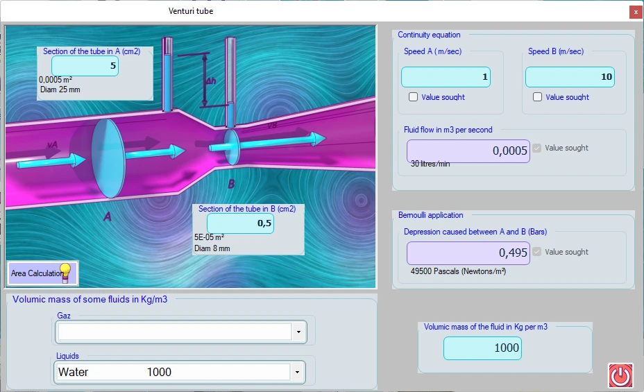
Detailed explanations and calculation in Mecaflux
The flow continuity equation :- Taking the average speed:
Section A x Speed A = Section B x Speed B = constant volume flow
- we deduce the velocity at point B
- We estimated in formulas continuity flow volume above, the fluid is incompressible. For a compressible fluid continuity equation must be applied to the mass flow rate:
Section A x Speed A= Section B xSpeed B = mass flow constant
- The equation of continuity applied to constant mass flow gives us:
Density A x Volume A x Section A = Density B x Volume B x SectionB
For all fumulas aboves:
- Density in kg/m3
- volume in m3
- section in m²
- spedd in m/sec
- volume flow in m3/sec
- mass flow in kg/sec
Frequently asked questions
Does the continuity equation apply to air?
Yes, in the form Q = S × V as long as the speed stays low compared with the speed of sound (below about 100 m/s the density changes by less than 5 %). In ventilation and air handling, air is therefore treated as incompressible. For compressed air, steam or a gas whose pressure or temperature changes, work with the mass flow ρ S V, or with the normal flow in Nm³/h referred to normal conditions.
Why does the velocity rise in a contraction, and what happens to the pressure?
Because the same volume of fluid has to pass through a smaller section in the same time. The energy needed for this acceleration is taken from the pressure: according to Bernoulli's theorem, the static pressure drops where the velocity rises, by ½ ρ (V₂² − V₁²). This is the principle of the venturi, used to measure a flow rate or to create suction.
What velocity should I choose in a pipe?
The velocity is limited to keep head losses, noise and erosion in check: for water, 1 to 2 m/s on the discharge side and 0.5 to 1.5 m/s on the suction side of a pump; for air, 3 to 5 m/s in ducts serving quiet rooms, 6 to 8 m/s in main ducts, 15 to 25 m/s for conveying dust or chips. The continuity equation then gives the diameter directly: D = √(4 Q / (π V)).
How do I calculate the velocities and diameters of my own network?
The duct sizing tool of Mecaflux Standard scans the commercial diameters for the required flow rate and displays, for each one, the velocity and the head loss with the fluid chosen among 120; the Bernoulli application of the software gives velocity and pressure at two points of a pipe of varying section. For a complete network to design or check, Mecaflux carries out the study of your project and delivers the calculation report, or offers training on the software applied to your own installation.