Page contents
What is the roughness of a pipe?
The absolute roughness ε (or k) of a pipe is the average height of the asperities of its inner wall, expressed in millimetres. Divided by the diameter, it gives the relative roughness ε/D used in the Colebrook equation to determine the friction factor λ in turbulent flow. A new steel tube has a roughness of about 0.05 mm, a PVC or copper tube 0.002 to 0.01 mm, old cast iron or rough concrete 1 to 3 mm. Roughness increases with age, corrosion and deposits, and the head loss with it.
Relative roughness and head loss
- ε: absolute roughness of the wall, in mm (or in m in the formula, same unit as D)
- D: inside diameter of the pipe
- λ: Darcy friction factor given by the Colebrook-White equation; Re: Reynolds number
Example: in a DN 50 pipe carrying water at 1.4 m/s (Re ≈ 70,000), going from new steel (ε = 0.05 mm) to corroded steel (ε = 1 mm) raises λ from 0.023 to 0.049: the head loss doubles.
Pipe roughness table
| Pipe material and condition | Roughness ε (mm) |
|---|---|
| PVC, PE, glass, new drawn tube | 0.0015 to 0.007 |
| Copper, brass, drawn stainless steel | 0.0015 to 0.01 |
| New steel, welded or drawn | 0.03 to 0.05 |
| New galvanised steel | 0.10 to 0.15 |
| Slightly rusted steel | 0.15 to 0.4 |
| Heavily corroded or scaled steel | 1 to 3 |
| New cast iron | 0.25 |
| Rusted cast iron | 1 to 1.5 |
| Scaled cast iron | 1.5 to 3 |
| Smooth concrete (steel formwork) | 0.3 to 0.8 |
| Rough concrete | 1 to 3 |
| Galvanised sheet ventilation duct | 0.10 to 0.15 |
| Flexible aluminium duct | 1 to 3 |
Roughness of welded steel pipes by condition
| Condition of the welded steel pipe | Roughness ε (mm) |
|---|---|
| New | 0.04 |
| New, bitumen-coated | 0.05 |
| Long in service, bitumen partly gone, corroded | 0.1 |
| Long in service, uniform corrosion | 0.15 |
| No significant unevenness at the joints; internally coated (about 10 mm layer); poor condition | 0.3 to 0.4 |
| Gas mains after many years of operation | 0.5 |
| Single or double transverse riveting; internally coated or uncoated, not corroded | 0.6 to 0.7 |
| Internally coated but oxidised; fouled by water in service, not corroded | 0.95 to 1 |
| Gas mains after 20 years of service, layered deposits | 1.1 |
| Double transverse riveting, not corroded; fouled by water in service | 1.2 to 1.5 |
| Light deposits | 1.5 |
Detailed explanations and calculation in Mecaflux
- The roughness is a key parameter in the calculation of major head loss in pipes..
- Roughness gives information on the state of the walls in contact with the fluid and acts on the surface friction.
- The roughness of the ducts is a determining factor in the choice of pipe materials in the study of a hydraulic system or ventilation
For practical purposes of calculating the unit varies depending on the application:
- For the study of major head loss in pipes and flat plates surface friction , we use the average roughness in millimeters (R). This is the average of the distances of the protrusions-hollows defect surfaces formed by ribs, grooves, slots or tearing:
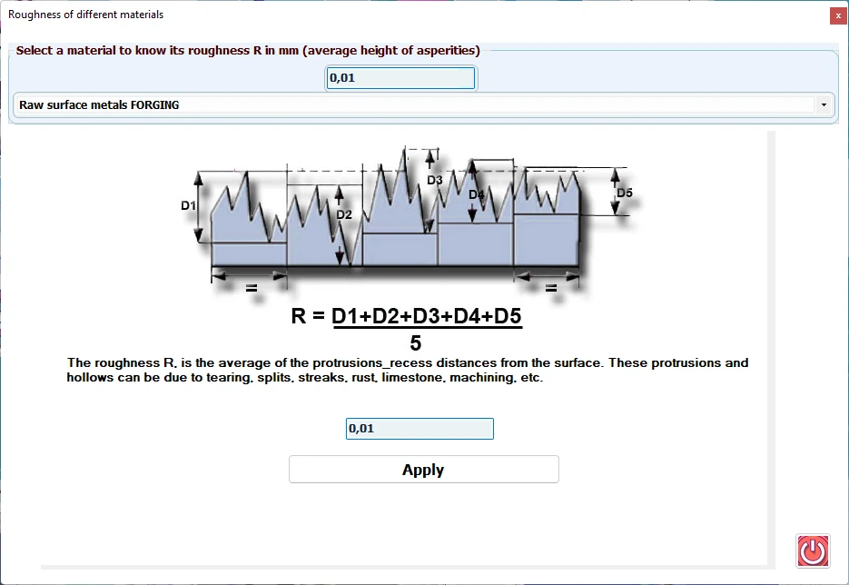
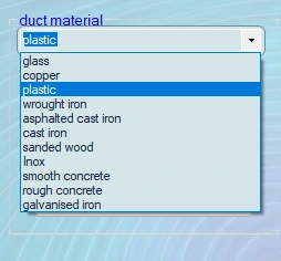
With Mecaflux standard software, you can get directly roughness (average roughness depth in millimeters) of the duct or pipe by choosing his material
- The formulas for the estimation of the flow regime (see Colebrook) using a ratio of the average roughness (R) on the diameter (D) of ducts, called relative roughness (D and R in the same unit):R/D
- into the frictional resistance on flat plate, a ratio of surface roughness, consisting of grains of sandwhose diameter, compared to the he bondary layer thickness is used. It is found that when the ratio exceeds 0.5 the roughness starts to play an important role in the frictional resistance on surface
- In naval hydrodynamics an average hull roughness is also used, using the equivalent roughness of grain sands(K), divided by the length of the hull(L):K/L(K and L in the same unit)
- The roughness of the pipes of a given material evolves over time according to the transported fluid (aggressive oxidant, acid, charged with abrasive material..) and operating conditions (constantly into water or exposure time to the air oxidation..). Conduct can become of a costly roughness operating energy and see its real price tenfold over time. The operating time is to apply to the evolution of roughness in the study of the purchase price of ducts. See: sizing Air and water pipes.
Mecaflux Editor roughness:
Choice of roughness according to the material, and the state of ventilation ducts, or hydraulic pipes in the software mecaflux.
more than 140 data roughness can cover all cases encountered in studies of air or water network
Examples of hydraulics networks pipe's roughness
Table roughness few conduits according to their status or number of years of service
Frequently asked questions
What is the roughness of steel?
About 0.03 to 0.05 mm for a new welded or drawn steel tube, 0.10 to 0.15 mm for galvanised steel, 0.15 to 0.4 mm for slightly rusted steel, and 1 to 3 mm for heavily corroded or scaled steel. For drawn stainless steel, 0.0015 to 0.01 mm.
What is the difference between absolute and relative roughness?
The absolute roughness ε is the average height of the asperities, in mm. The relative roughness is the ratio ε/D, dimensionless: this is what matters for the head loss, because the same asperity disturbs the flow far more in a small tube than in a large pipe.
How does roughness affect the head loss?
In turbulent flow, the higher the relative roughness, the higher the friction factor λ, and therefore the higher the head loss at equal flow rate. In laminar flow (Re < 2,000), roughness has no effect: λ = 64/Re.
Which roughness should I use for the pipes of my own installation?
In the major head loss tool of Mecaflux Standard you pick the material and condition of the pipe from a roughness table (new or corroded steel, cast iron, PVC, concrete, copper, hoses) and the software applies it to each run of the inventory; you can also enter your own value for an aged pipe. For an old network to diagnose or a new one to size with end-of-life roughness, Mecaflux carries out the study of your project, or offers training on the software applied to your own pipes.