Page contents
What is the angle of attack of an aerofoil and how does it act on lift and drag?
The angle of attack (or angle of incidence) α is the angle between the chord of the aerofoil and the direction of the oncoming fluid. It is the main control of lift: as long as the flow stays attached, the lift coefficient grows linearly with the angle of attack, by about 0.1 per degree (thin aerofoil theory: 2π per radian), from the zero-lift angle α₀ (0° for a symmetrical section, −2 to −4° for a cambered one). Drag, small at low angles, grows with the square of the lift. Beyond 12 to 16° the boundary layer separates from the upper surface: this is the stall, lift collapses and drag soars. Example: a 1 m² wing with a NACA 0012 section, in air at 20 m/s (dynamic pressure 245 Pa), lifts 108 N at 4° and 299 N at 14°, then only 257 N at 16°, after the stall.
Lift formulas against angle of attack
- α: angle of attack, in degrees, between the chord and the flow direction; α₀: zero-lift angle of the section
- CL: lift coefficient, dimensionless; the slope of 0.11 per degree (2π per radian) holds for attached flow on a section of infinite span, a little less for a real wing
- CD: drag coefficient, read on the polar of the section at the same angle and the same Reynolds number
- ρ: density, in kg/m³; V: relative velocity, in m/s; S: wing area, in m²
- FL, FD: lift and drag, in N
Lift and drag of a 1 m² wing against angle of attack
| Angle of attack α | CL | CD | Lift FL | Drag FD | L/D |
|---|---|---|---|---|---|
| 0° | 0 | 0.0065 | 0 N | 1.6 N | 0 |
| 2° | 0.22 | 0.0070 | 54 N | 1.7 N | 31 |
| 4° | 0.44 | 0.0080 | 108 N | 2.0 N | 55 |
| 6° | 0.66 | 0.0095 | 162 N | 2.3 N | 69 |
| 8° | 0.86 | 0.0115 | 211 N | 2.8 N | 75 |
| 10° | 1.03 | 0.0145 | 252 N | 3.6 N | 71 |
| 12° | 1.15 | 0.019 | 282 N | 4.7 N | 61 |
| 14° | 1.22 | 0.028 | 299 N | 6.9 N | 44 |
| 16° (stalled) | ≈ 1.05 | ≈ 0.07 | ≈ 257 N | ≈ 17 N | ≈ 15 |
Zero-lift and stall angles of a few sections
| Section | Zero-lift angle α₀ | Stall angle | Maximum CL |
|---|---|---|---|
| Thin flat plate | 0° | ≈ 8° | ≈ 0.8 |
| NACA 0012 (symmetrical) | 0° | ≈ 15° | ≈ 1.25 |
| NACA 2412 | ≈ −2° | ≈ 16° | ≈ 1.5 |
| NACA 4412 | ≈ −4° | ≈ 14° | ≈ 1.55 |
| Clark Y | ≈ −3° | ≈ 15° | ≈ 1.45 |
Detailed explanations and calculation in Mecaflux
In aerodynamics or hydrodynamic, the angle of incidence or the angle of attack is the angle that forms the chord of the profile with a fluid stream..
- For oblique plate immersed in the fluid incidence angle is the angle formed by its sides with the overall trajectory of the fluid.
- For an airfoil or spoiler, daggerboard or sail, incidence profile, is the angle formed by the profile chord related to the general path of the fluid.
the angle of incidence or attack is an important parameter in the calculation of the drag and lift..
with Mecaflux standard
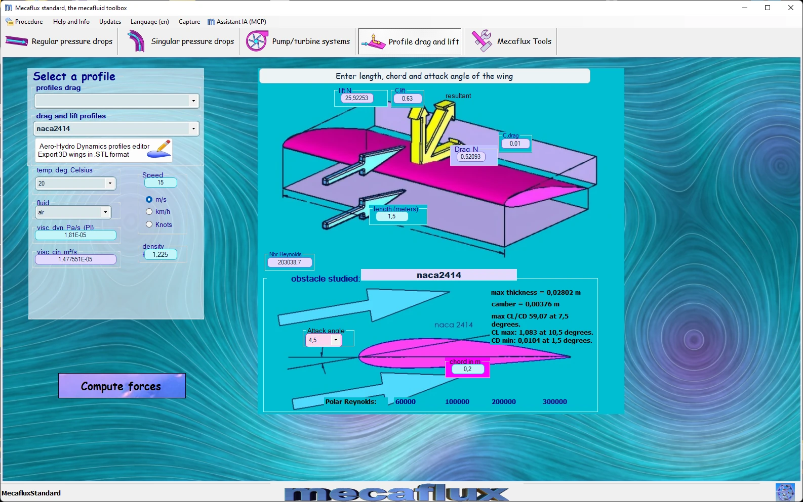
The mecaflux software offers 11 different profiles at various angles of incidence or attack
Frequently asked questions
What is the difference between angle of attack, setting angle and pitch attitude?
The angle of attack is the angle between the chord and the relative wind: it is what sets the lift. The setting angle (rigging angle) is the angle between the chord and the reference axis of the craft (fuselage, hull, propeller blade): it is fixed at construction. The pitch attitude is the angle between that axis and the horizontal. On a propeller, the angle of attack of each section results from the setting (pitch) and the relative velocity, made of the advance speed and the rotational speed.
What is the stall and at what angle does it occur?
Beyond a certain angle of attack the flow can no longer follow the curvature of the upper surface: the boundary layer separates, a region of eddies replaces the suction that was carrying the wing, lift collapses and drag rises sharply. The critical angle is 12 to 16° for most sections, only 8° for a flat plate, and decreases at low Reynolds numbers. High-lift devices (flaps, slats) push it back.
What angle of attack should I choose for a wing, a fin or a propeller?
That of the maximum lift-to-drag ratio, between 4 and 8° for a conventional section, when efficiency matters most (cruise, glider, propeller, wind turbine); a higher angle, close to the maximum CL, when a lot of lift is needed at low speed (take-off, keel when close-hauled). Always keep a margin of 2 to 3° below the stall, since gusts and speed changes alter the actual angle of attack.
How do I find the best angle of attack for the section of my own wing, fin or propeller?
In the drag and lift tab of Mecaflux Standard you choose one of the 11 sections, the fluid, the speed, the chord and the span, then vary the angle of attack: the software displays lift, drag and lift-to-drag ratio for each angle, with the diagram of the section. Heliciel itself sets the angle of attack of each blade or wing element at the best lift-to-drag ratio of its section and derives the 3D geometry of the propeller or wing. For a project to design or improve, Mecaflux carries out the study of your project, or offers training on the software applied to your own case.