Page contents
How do I calculate the Reynolds number and interpret the flow regime?
The Reynolds number compares the inertial forces of a flow with its viscous forces: Re = ρ × V × L / μ = V × L / ν, dimensionless, where V is the velocity, L a reference length (the bore for a pipe, the chord for an aerofoil) and ν the kinematic viscosity of the fluid. It sets the flow regime: in a pipe, laminar below 2,000, transitional between 2,000 and 3,000, turbulent above. Example: water at 20 °C (ν = 1.0 mm²/s) at 1 m/s in a DN 50 pipe of 53.1 mm bore gives Re = 1 × 0.0531 / 10⁻⁶ = 52,900, clearly turbulent; the flow would only stay laminar below 0.038 m/s. In air (ν = 15.1 mm²/s) the Reynolds number is 15 times lower for the same velocity and dimension. The calculator below gives the Reynolds number of a pipe, an aerofoil, a plate or a bluff body, with the corresponding regime and the transition velocities.
Reynolds number formulas
- Re: Reynolds number, dimensionless; in a pipe: laminar if Re < 2,000, transitional from 2,000 to 3,000, turbulent above
- ρ: density of the fluid, in kg/m³; μ: dynamic viscosity, in Pa·s (water at 20 °C: 1.0 × 10⁻³); ν = μ/ρ: kinematic viscosity, in m²/s
- V: average velocity of the fluid, in m/s, V = 4 Q / (π D²) in a pipe; relative velocity for a moving body
- L: reference length, in m: bore D (or hydraulic diameter) of a pipe, chord of an aerofoil, wetted length of a plate, frontal width of a bluff body
Reynolds number and regime of water in a DN 50 pipe against velocity
| Velocity V | Flow rate | Reynolds Re | Regime | Friction factor λ |
|---|---|---|---|---|
| 0.01 m/s | 0.08 m³/h | 530 | laminar | 64/Re = 0.121 |
| 0.03 m/s | 0.24 m³/h | 1,590 | laminar | 64/Re = 0.040 |
| 0.05 m/s | 0.40 m³/h | 2,650 | transitional | uncertain |
| 0.1 m/s | 0.80 m³/h | 5,290 | turbulent | Colebrook: 0.037 (new steel) |
| 0.5 m/s | 3.99 m³/h | 26,500 | turbulent | 0.026 |
| 1 m/s | 7.97 m³/h | 52,900 | turbulent | 0.023 |
| 2 m/s | 15.9 m³/h | 105,800 | turbulent | 0.022 |
Reynolds number of some common flows
| Flow | Reference length L | Velocity V | Re | Interpretation |
|---|---|---|---|---|
| 1 mm ball falling in water | 1 mm | 0.1 m/s | 100 | laminar wake, CD ≈ 1.1 |
| VG 46 oil at 40 °C in a DN 25 pipe | 27.3 mm | 1 m/s | 590 | laminar: λ = 64/Re |
| Air in a 300 mm duct | 300 mm | 5 m/s | 99,600 | turbulent |
| Drone wing | chord 0.15 m | 15 m/s | 149,000 | low Reynolds: polars sensitive to Re |
| Wind turbine blade | chord 1 m | 60 m/s | 4.0 × 10⁶ | turbulent boundary layer, high lift-to-drag ratio |
| Light aircraft wing | chord 1.5 m | 50 m/s | 5.0 × 10⁶ | same |
| Marine propeller blade | chord 0.3 m | 15 m/s | 4.3 × 10⁶ | same, in water |
| 10 m hull in sea water | 10 m | 5 m/s (9.7 knots) | 4.8 × 10⁷ | friction from the ITTC 1957 line |
Detailed explanations and calculation in Mecaflux
- Reynolds gave us a bridge between the different fluids and different scales
- The inside diameter of the duct (for flows in pipes)
- For the study of the geometric body drag, unshaped, this reference length is the width of the frontal area (perpendicular to flow)
- For the study of the lift, the drag of profiled bodies, this length is measured parallel to the flow.
- For the Study of the drag friction flat surface, the reference length is the length of the wetted area, taken parallel to the flow.
Re=V.L/u
Re = ((average speed) x (reference length)) / (kinematic viscosity of the fluid)or also
Re = ((mass per units volume) x (average speed) x (reference length)) / (dynamic viscosity of the fluid)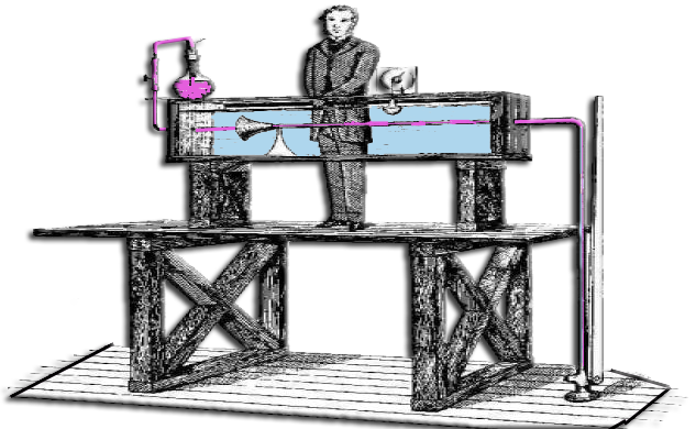
Frequently asked questions
Which reference length should I use in the Reynolds number?
The one that governs the phenomenon studied, and always the same as in the curves or correlations you use. For pipe flow it is the bore, or the hydraulic diameter 4 S / P for a non-circular section. For the lift and drag of an aerofoil it is the chord; for the friction of a plate or a hull, the wetted length along the flow; for a bluff body (sphere, cylinder), the frontal dimension. The same Reynolds number of 10⁵ therefore does not mean the same thing for a pipe and for a wing.
Why the thresholds of 2,000 and 3,000 in a pipe?
Below 2,000 every disturbance dies out and the flow stays laminar: the head losses follow Poiseuille's law, λ = 64/Re, proportional to the velocity and independent of roughness. Above 3,000 turbulence sustains itself and the losses vary roughly as the square of the velocity, according to Colebrook. In between, the regime depends on upstream disturbances and on roughness: calculations there are uncertain and one avoids sizing a network in that zone. These thresholds only apply to pipes: an aerofoil or a sphere have their own transitions, around 5 × 10⁵.
What is the Reynolds number used for with models and similarity?
Two flows with the same geometry and the same Reynolds number are similar: they have the same drag, lift or friction coefficients. This is what allows a one-tenth scale model to be tested in a wind tunnel or a towing tank, provided the speed is increased or the fluid changed to recover the full-scale Reynolds number, which is not always possible. It is also why the polars of an aerofoil are given per Reynolds range, and why a section that is excellent on an aircraft can disappoint on a small propeller or a drone, which work at Reynolds numbers a hundred times lower.
How do I know the flow regime of my own network or aerofoil?
Mecaflux Standard calculates the Reynolds number and the regime of each pipe section, picks the appropriate head loss equation and warns you of cases close to the transition; for aerofoils it holds polars over 3 Reynolds number ranges and extrapolates outside them. For a network or an aerodynamic project to design or check, Mecaflux carries out the study of your project and delivers the calculation report, or offers training on the software applied to your own case.