Page contents
What is a minor head loss?
A minor head loss (also called local or singular head loss) is the pressure drop caused by a fitting that disturbs the flow: bend, tee, valve, check valve, change of section, tank inlet or outlet. It is calculated by multiplying the dynamic pressure of the fluid, ρV²/2, by a loss coefficient K (also written ζ or ξ) specific to each fitting. It adds to the major head losses of the straight pipe runs to give the total head loss of the system.
Minor head loss formula
- ΔP: minor head loss, in pascals (Pa); ΔH: the same loss in metres of fluid column (ΔP = ρ g ΔH)
- K: loss coefficient of the fitting, dimensionless (see the table)
- ρ: density of the fluid, in kg/m³
- V: mean velocity of the fluid in the reference pipe, in m/s
- g: 9.81 m/s²
Example: water (ρ = 1,000 kg/m³) at 1.5 m/s through a sharp 90° elbow (K = 1.2): ΔP = 1.2 × 1,000 × 1.5² / 2 = 1,350 Pa, i.e. ΔH = 0.14 m. For a contraction or an expansion, V is the velocity in the smaller section.
Table of minor loss coefficients K
| Fitting | Coefficient K |
|---|---|
| Long-radius 90° bend (r/D ≥ 1) | 0.2 to 0.3 |
| Sharp 90° elbow | 1.1 to 1.3 |
| 45° bend | 0.2 to 0.4 |
| Tee, straight run | 0.3 to 0.4 |
| Tee, branch flow | 1.0 to 1.5 |
| Gate valve, fully open | 0.1 to 0.2 |
| Butterfly valve, fully open | 0.2 to 0.5 |
| Ball valve, fully open | 0.05 to 0.1 |
| Globe valve, fully open | 4 to 10 |
| Swing check valve | 2 to 3 |
| Sharp-edged pipe entrance (from a tank) | 0.5 |
| Rounded pipe entrance | 0.05 |
| Pipe exit into a tank | 1.0 |
| Sudden contraction, area halved | 0.3 to 0.4 |
| Sudden expansion, area doubled | 0.25 (= (1 − A₁/A₂)²) |
| Clean strainer | 1 to 3 |
Detailed explanations and calculation in Mecaflux
Minor head loss (or elements pressure drop) are expressed in fluid heights (meters) in pascals or bars.- DH is the pressure drop of major head loss in meter column fluid
- l is the major head loss coefficient
- V is the average flow velocity
- g is graity (9.81)
-
Minor head loss (or elements pressure drop) of aeraulic and hydraulic networks are pressure losses caused by the passage of fluid through obstacles and accessories such as valves, fittings, expansion, exit tank, extractor hood etc ... .
-
the Minor head loss are expressed in Pascals, in meters fluid columns (m), or in equivalent meters of straight pipe.. the Minor head loss are also named elements pressure drop. These are the pressure losses due to elements encountered in the fluid path.
-
Minor head loss coefficients are given for the usuals elements of fluid's networks. In general, these data are provided by the manufacturers of hydraulic accessories. Some formulas used to calculate these coefficients, as Weisbach formula for elbows or Lorenz for divergent cones.
- Editor minor head loss elements
- table coefficients
- Internal flow exemple
- Valve pressure drop
- Formula pressure drop head loss
With MECAFLUX:
Curves of losses of one hundred basic accessories are available and configurable il Mecaflux standard software. (Example closing angle of hydraulic valve, the number of guide vanes in an elbow aeraulic ...)
The minor head loss coefficient is automatically based on parameters you enter..The minor head loss coefficient selected in the graph and the computed pressure drop caused by aeraulic or hydraulic accessories that you have chosen, is given to you in the results sheet.
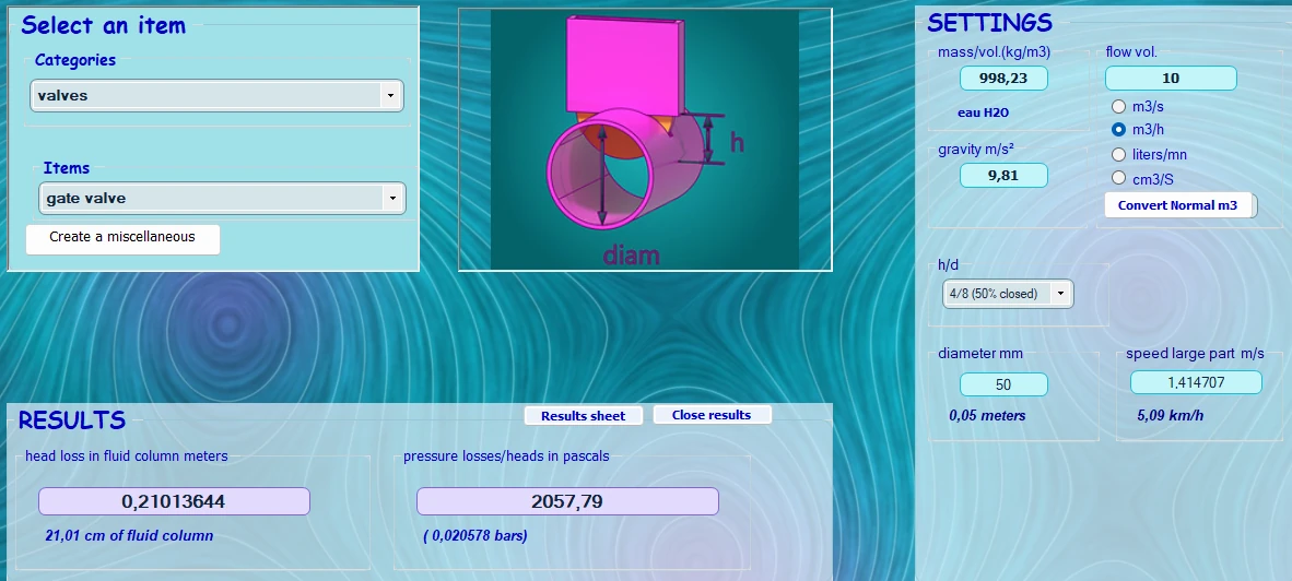
The chart interface selection and parametrage elments pressure loss (minor head loss) in MECAFLUX:
here a gate valve
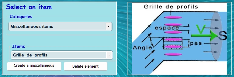
a grid composed of profile bars
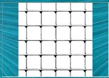
a perforated plate filter
calculation procedure with mecaflux:
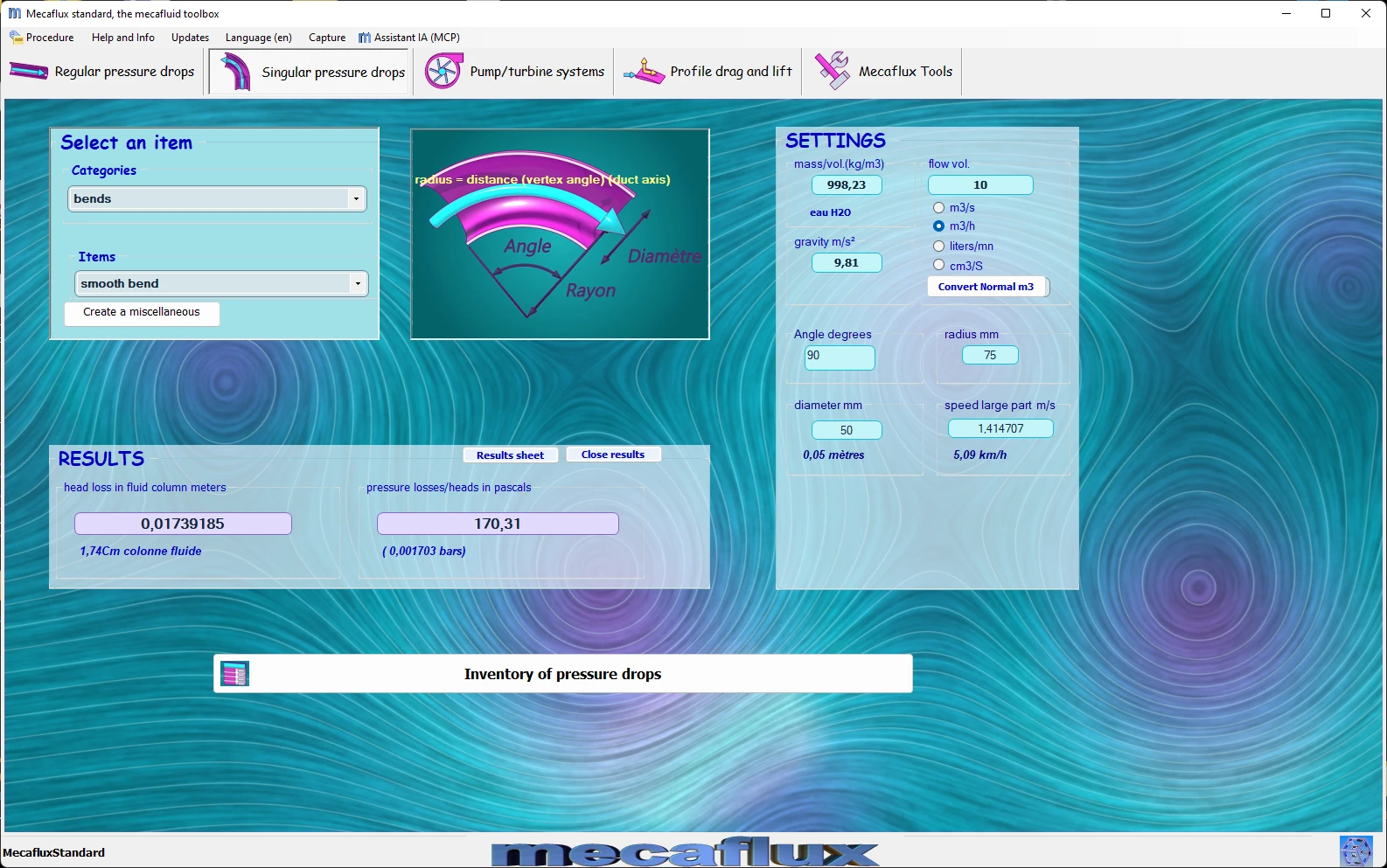
- select an aeraulicor hydraulic accessories, choosing a "category" and "element" (nomogram of a hundred different accessories)
- fill in the fields with blue text under "parameters"
- cliquez sur calculer
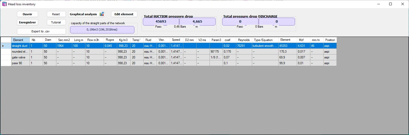
ou can add elements to the list of minor pressure losses elements.To do this a nomogram element editor is available.
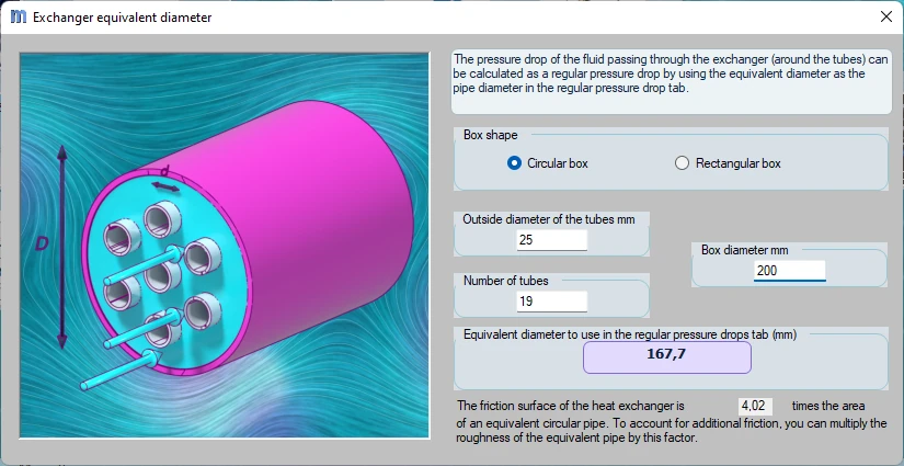
the losses in the heat exchangers is treated in regular elements:
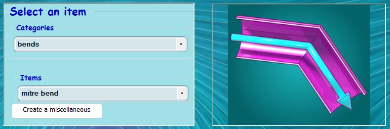
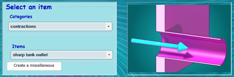
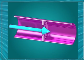
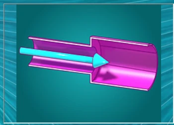
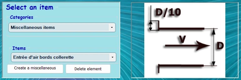
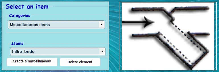
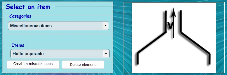
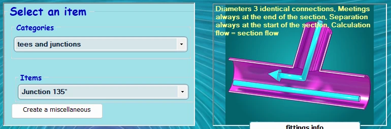
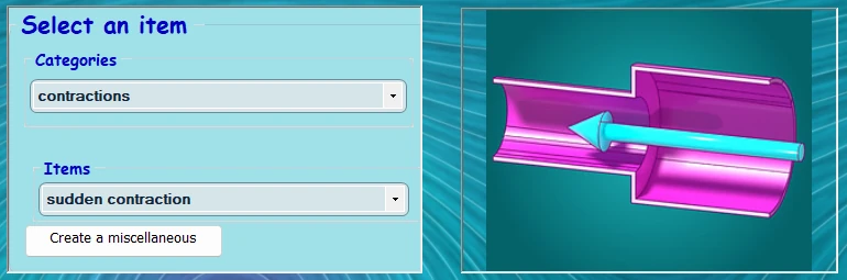
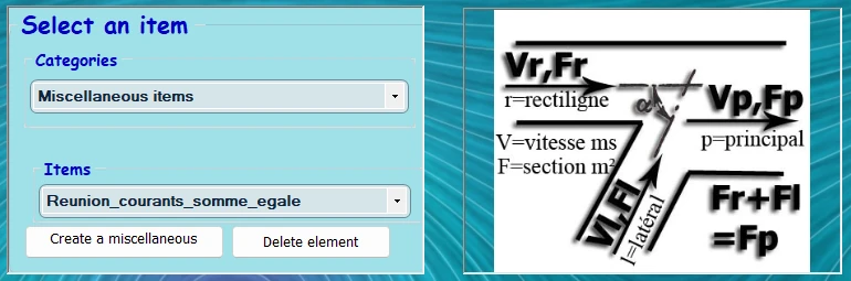
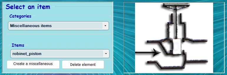
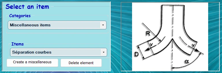
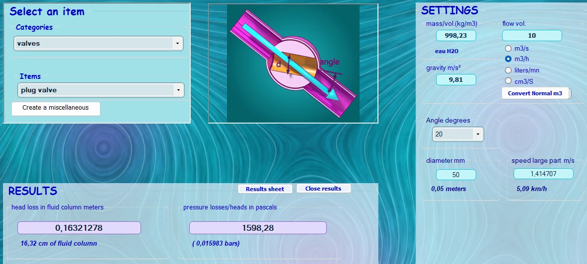
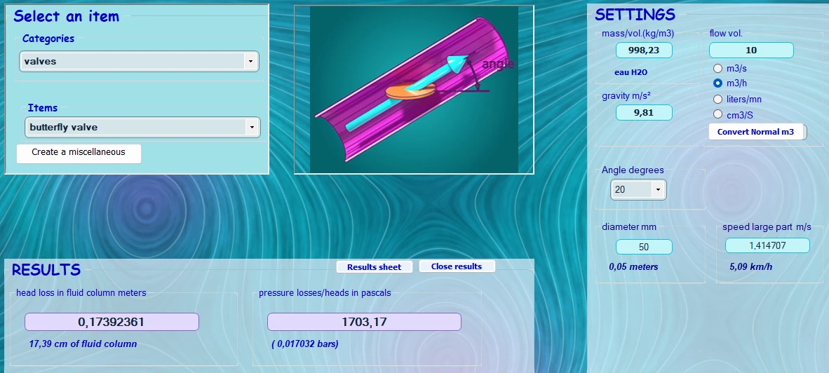
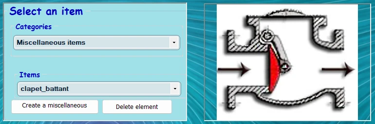
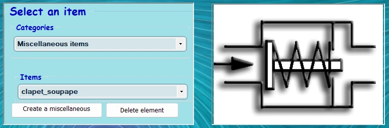
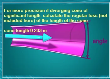
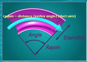
Exemples of charts for minor head loss coefficients of some usual éléments in a fluid network


Frequently asked questions
What is the difference between major and minor head losses?
The major loss comes from the friction of the fluid on the wall of a straight run: it is proportional to the length and is calculated with the friction factor λ (Colebrook). The minor loss is localised in a fitting and is calculated with a coefficient K. The total head loss of the system is the sum of both.
Where do I find the K coefficient of a specific fitting?
In the manufacturer's documentation, as a K coefficient, a pressure drop curve or a Kv value (valves). Otherwise, Idelchik's tables or the orders of magnitude above. The Mecaflux Standard software includes a chart of about a hundred adjustable fittings.
What is the equivalent length of a fitting?
It is the length of straight pipe that would produce the same head loss as the fitting: Leq = K × D / λ. It allows straight runs and fittings to be added up as a single fictitious length.
How do I add up the minor head losses of my own network?
The head loss inventory of Mecaflux Standard holds a database of K coefficients for bends, tees, valves, enlargements and contractions: you add each fitting of your network with its diameter, and the software adds the minor and major losses to plot the system curve and find the pump operating point; Mecaflux Pro3D does the same balance on a network drawn in 3D with its branches. For an existing network or a project to justify, Mecaflux carries out the study of your project, or offers training on the software applied to your own installation.