Mecaflux, The software allows the calculation of the thermal flow, and the size of duct flue but for those who do not have the software,
here is the calculation method used for the evaluation of the diameter of flues, heat flow duct, and flue gas flow rate, depending on power, on the type of boiler and its performance.
This method of determining the diameters of flue is based on the DTU which is downloadable from this link: Assistance Sizing Ducts Smoke :DTU 12/75 (P 51-701) valid only natural heat flow and for S P inst > 75 th/h
Sizing diameter flue or chimney must comply with the rules relating to pollution, setting an exhaust velocity, depending on the sulfur content, but also the principle of circulation, computed with Bernoulli , depending on smoke pipe head loss , the chimney height and the temperature difference between the inlet and the outlet flue gas discharge duct.
What we are concerned primarily in our calculation and dimensioning of flue pipe or chimney , this is the minimum speed of smoke emission. The minimum speed to be respected, we will check if the generator and smoke evacuation system realize this circulation condition. We will discuss here the rules of minimum rates of emissions that should ensure the conduit, depending on the sulfur content in flue gas. But regulation of smoke emissions far beyond this framework.
- The minimum speed smoke exhaust duct must be for the rated power of the smallest boiler debiting alone in the duct, greater than or equal to the minimum emission rate as defined below :
operating mode generators |
Power burner [th/h]/PCI |
Sulfur content "x" of the fuel [g/th]/PCI |
|||
< 0,10 |
0,10 < x < 1 |
1 < x < 2 |
2 < x |
||
All or Nothing |
P < 8000 |
2 |
2 |
5 |
|
P > 8000 |
2 |
3 |
6 |
|
|
continuous |
|
3 |
3 |
6 |
|
modulated |
P < 8000 |
4 |
6 |
9 |
9 |
P > 8000 |
4 |
6 |
9 |
12 |
|
- operating All or Nothing :The generator is operating at its rated pace or does not work
- operating continuous :The power burner is never less than 66% of the nominal power.
- operating modulated :Power to the burner may be less than 66% of the nominal power.
Knowing now the minimum speed smoke exhaust, we need the flow of flue, to know the right size pipe..
an estimate of the flow rate of smoke (in the absence of boiler manufacturer data) can be calculated from the power of the boiler or generator and the excess air.
the excess air can be estimated from the type of generator
Average values ??of excess air:
- Average values ??of excess air:
- Coal: e = 70%
- Oil: e = 45%
- Gas: e = 30%
- Wood logs: e = 50%
- Wood Granulated: e = 30%
the flue gas flow rate will be estimated by the formula:
With flue mass flow :[kg/h], e:% excess air, P :Power burner [th/h]/PCI
As you have probably noticed the flue gas flow rate is given here in mass flow, to convert in volume flow, we need to know the average density of flue gas. A table of the flue gas density estimated in function of the temperature is provided in mecaflux. But not to leave you stranded if you do not have mecaflux here is the density of smoke at 150 °:0.9 kg/m3 and at 50 °1.1 . The temperature is crucial to estimate the smoke density in the conduit.
This density is also necessary to calculate the actual movement speed of the smoke in the pipe , because the minimum standard of speed and flow rate of smoke from the boiler does not tell us whether the thermal chimney flue works!! . So the temperature of duct inlet is necessary to go further.Fluid temperature (smoke) is given by the manufacturer or by default in the following table:
Combustion efficiency hc |
fuel |
excess air % |
||||
5 % |
15 % |
30 % |
45 % |
60 % |
||
96 % |
Gaz |
95 |
88 |
|
|
|
|
heating oil |
103 |
95 |
|
|
|
94 % |
Gaz |
142 |
132 |
118 |
107 |
98 |
|
heating oil |
156 |
142 |
127 |
115 |
105 |
92 % |
Gaz |
190 |
176 |
157 |
143 |
131 |
|
heating oil |
208 |
190 |
170 |
153 |
140 |
90 % |
Gaz |
238 |
220 |
198 |
179 |
164 |
|
heating oil |
260 |
238 |
212 |
191 |
175 |
88 % |
Gaz |
286 |
264 |
236 |
215 |
197 |
|
heating oil |
310 |
286 |
254 |
229 |
209 |
86 % |
Gaz |
332 |
308 |
275 |
250 |
230 |
|
heating oil |
362 |
332 |
297 |
268 |
244 |
the outside temperature is taken equal to :
. 18 °C for boilers operating in WINTER only
. 30 °C for boilers operating throughout the yearExemple :
if hc = 94 % for gas with 15 % excess air, is obtained for a boiler running throughout the year:
Temp flues = (132 - 30)
Temp flues = 102 °C at the entrance to the chimney.
the average temperature in the conduit is slightly lower than the inlet temperature, because the smoke cooled down in contact with the walls of the duct. we estimate the loss of temperature depending on the length and type of duct according to the following approximate temperature drop :- - 3 °C/ml for metal chimneys
- - 1,5 °C/ml for masonry chimneys
- - 0,8 °C/ml for insulated chimneys
The average temperature in the pipe will be approximately equal to (inlet temperature + temperature output)/2. (this is an approximation because in reality the average temperature evolves differently)
with the average temperature we select the average density in the duct, So we can estimate the approximate diameter pipe that carries the speed requested by the rule of pollution
section m� = (mass flow X average density) / minimum velocity of flue pipes.
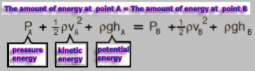
To verify that our system works, we need to check if the stack effect, caused by the density difference between the outside air and the average density of the flue in the duct, providing heat circulation
For this we use the Bernoulli, which gives the relationship between the energy of static and dynamic pressure
the driving pressure is reduced by pressure resistant: pressure drops of the conduit and the boiler and also the pressure in the boiler room (about 2.5 Pascals by lack of wind)
The actual speed in the duct can be evaluated as :
velocity=sqrt(((driving pressure - resistant effect)X2)/average density in the duct)
so we check that speed is greater than the rule of pollution.
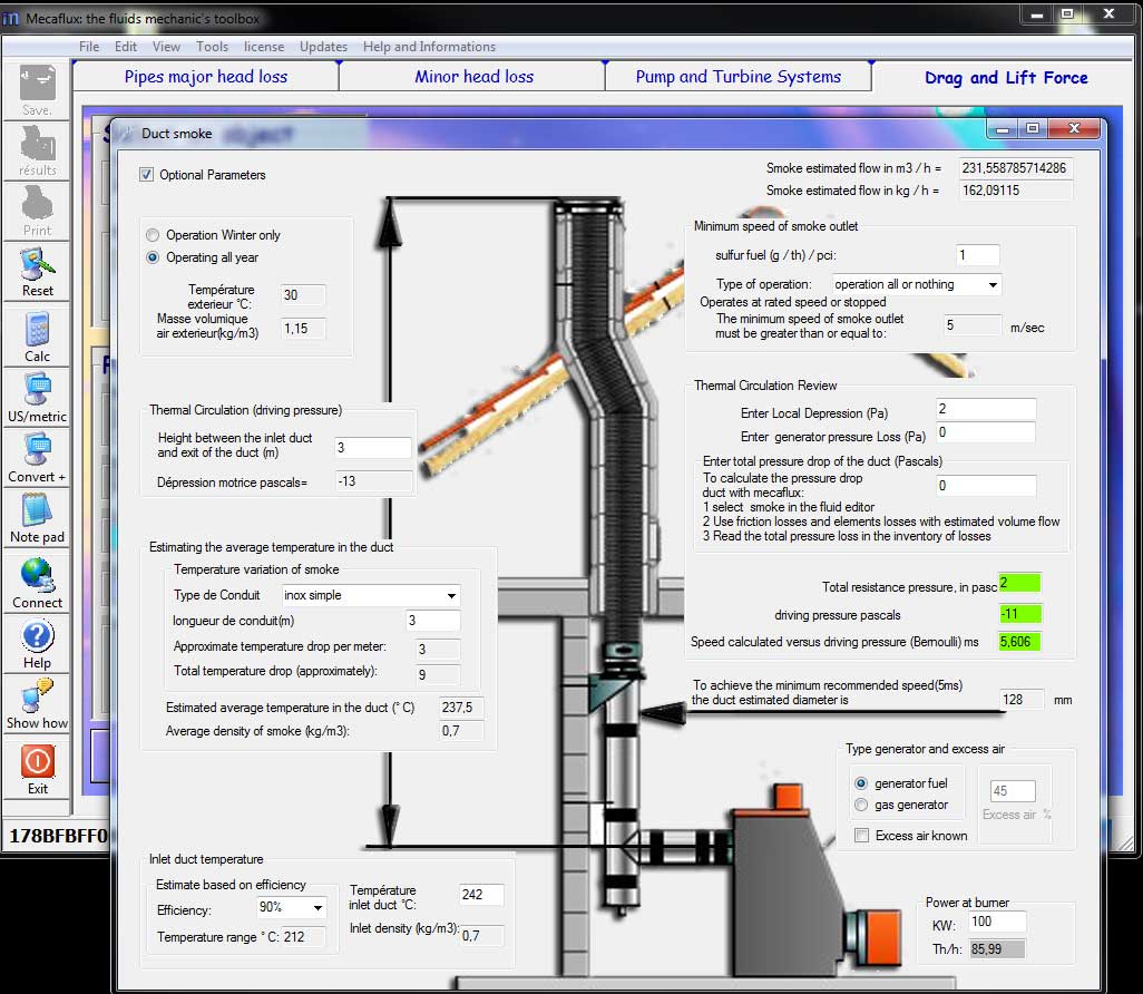
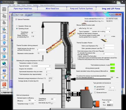
the design method and calculation of flue pipe, mentioned above, is integrated in the software mecaflux menu tool/ flues.
This tool allows you to quickly know and estimate the duct diameter and length depending on the parameters of the heating system.
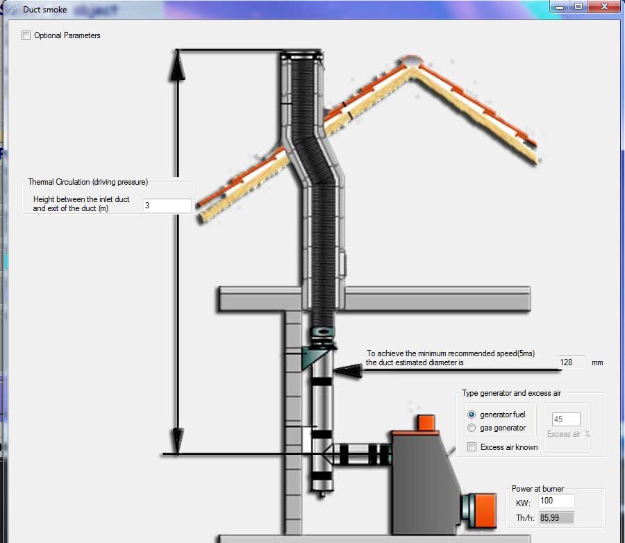
A simplified mode, gives the diameter to be applied to realize a velocity in the pipe, depending on the generator and the excess air, and a mode with more options, allows you to enter the advanced parameters ...
Simplified calculation of pipes flue:
Mecaflux The software allows the calculation of the diameter of flue pipe, depending on various parameters such as boiler efficiency, the sulfur content, the height of the duct, the pressure drop, the pressure in the boiler room, or temperature entry into the flue duct...