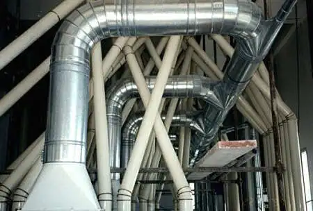
The suction or ventilation is produced by a vacuum generated by a pump or turbine propeller fan. The suction velocity must be sufficient to perform particle transport, that we must aspire, or ventilate the area with sufficient capacity meeting the standards.
In the case of a vacuum for carrying particles, the conveying speed is calculated in relation to the speed of sedimentation . We seek a maximum speed in the ducts, and the limit is imposed by the vacuum generated by the turbine.
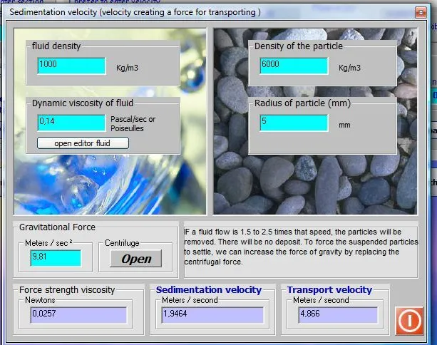
The suction speed and therefore transport of dust, chips or other materials, is simply calculated using this interface. Suffice it then ensure that this minimum requirement is met. For this, the pump or fan of aspiration, should be strong enough to balance the the head loss in the extraction system. A calculation of losses, in accordance with the flow rate of minimum suction must be made.
If one wishes to make the propeller axial fan, generating pressure balancing the pressure drop at the desired speed we can use the software to design propellers and fans, héliciel.
In cases where ventilation is intended to renew, or filter, the air in a volume defined, lThe speed is limited by the noise and it meets standards according to local.
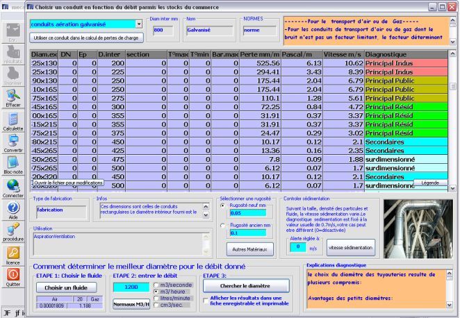
To find a good compromise between the purchase price, installation, operation, pumping, roughness, trade stock, An interface to aid sizing the ventilation ducts, or hydraulic, is integrated into mecaflux.
lthe energy consumed by the pump and the efficiency of the vacuum are related:
- To the head loss in the suction conduits
- the pressure in the tank of aspiration
- Performance of this pump
- the suction head for heavy fluids such as liquid (vertical dimension from the pump shaft to the surface of the suction tank) this height is directly related to the hydrostatic load
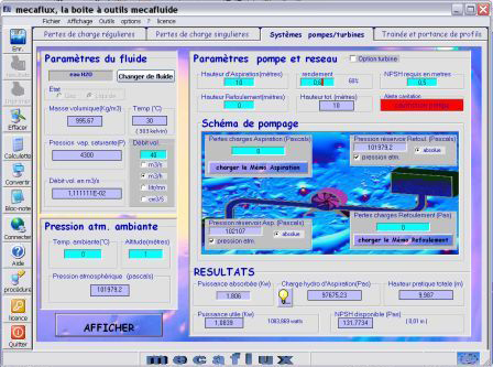
Parameters basics of power 'aspirations are easily found in the pump / turbine systems interface after a calculation of losses.
- If the network suction is branched, the balancing of the the head loss in the branches determines the suction flow in the branches. For branched systems we save time with Mecaflux pro 3D because its 3D interface is suitable for branched networks. See tutorial system aspiration mecaflux pro 3D
- With mecaflux standard, we can do several iterations to calculate the head loss in each branch to find the flow balance, But it gets complicated when the number of branches to balance increases.
Tutorial mode selection aspiration: use the aspiration mode to create the suction systems
Networks and suction Air and water systems AERAULIC or hydraulic systems
For the calculation of the propeller optimum for aspiration, we can use the software to design propellers and fans:Heliciel