The flow rate that delivers a centrifugal pump or fan decreases depending on the pressure resistant (load height or Delta pressure) of the fluid's network. This resistance of the network is the pressure that must provide the pump or fan, to achieve a given rate.
the manufacturer provides with the pump, a flow curve of evolution, as a function of the pressure resistant, that the pump has to overcome.. The curves are generally provided for a family of pump. Pressure (or delta P for the fans), is given in Hm (manometric head) for liquids, or Pascals for aeraulic.
- As a simple reminder, 1 meter water column produces a pressure (Density X Gravity X Height) 1000 x 9,81 x 1 = 9810 pascals. 1 bar=100 000 pascals we note that 1 bar = 10 water meters = 100 000 pascals
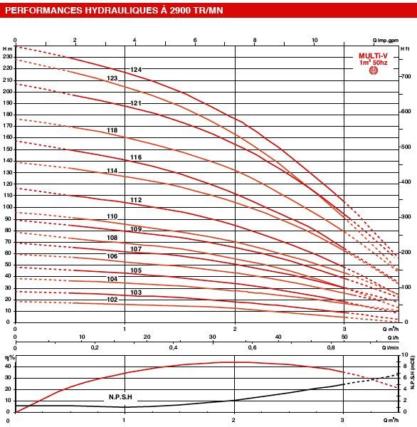
Pump wheel diameter reduced: In theory the flow and manometric head are proportional to the square of the diameter of the wheel. wheel diameter reduced is used to modify the pump flow without modifying its performance, (in a limit of 15% of the initial diameter), This therefore gives the possibility to manufacturer, to using a model of pump to produce a range of pumps perfectly adapted to various specifications.
We see for example that the pump with wheel 116 mm provides a pressure of 110 Meters, to flow rate of 2 m3 /h in its area of best efficiency (about 42% ). Here we can read the graph of the pump, It remains to see if it corresponds to our network. The question that arises is: What is the pressure required to circulate the fluid in our system, to the flow rate that we want to achieve? At the flow rate that we want to achieve, the pressure provided by the pump must be equal to the sum of:- head loss (friction losses and turbulence in the conduct constituting the system and Accessories. See major head loss and minor head loss))
- static pressure: Height difference between the point of input and output circuit (zero if the network is closed. See hydrostatic head)
- Dynamic pressure: acceleration of the fluid, it is the kinetic-energy (speed) supplied to the fluid.
- The operating point of the system "pump / network" is the flow rate that balances the pressure supplied by the pump and pressure necessary for the operation of the network flow.
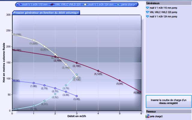
- The yellow curve intersects the curve network, to operating point 3 m³/h
- The dark blue curve intersects the curve network, to operating point 2,2 m³/h
- The red curve pump is outside the range of flow in which the network was tested (light blue curve) But we can imagine that if the curve network continues to evolve in this way, it crosses the red line at the operating point of 3,5 m³/h
Another example video: