Page contents
How do I calculate the major head losses of a pipe?
Major head losses (friction losses) are the energy the fluid loses by friction along a straight pipe of constant section. They are calculated with the Darcy-Weisbach formula, ΔH = λ × (L / D) × V² / (2 g), in metres of fluid column, or ΔP = ρ g ΔH in pascals. The friction factor λ equals 64/Re in laminar flow and is calculated with the Colebrook equation in turbulent flow, from the Reynolds number and the relative roughness ε/D. Example: 10 m³/h of water at 20 °C in 100 m of DN 50 steel pipe (53.1 mm bore, ε = 0.045 mm): V = 1.25 m/s, Re = 66,400, λ = 0.0227, ΔH = 3.43 m, i.e. 33.6 kPa (0.34 bar). The calculator below does this calculation for water, air, oils or any fluid whose properties you enter, with the roughness of the chosen material, and plots the system curve of the section.
Major head loss formulas
- ΔH: head loss, in m of fluid column; ΔP: the same in Pa (water: 1 m = 9.8 kPa); the loss per unit length j = ΔH/L is given in mm/m or Pa/m
- λ: friction factor, dimensionless (0.015 to 0.06 in practice); L: pipe length, in m; D: bore, in m (hydraulic diameter for a non-circular section)
- V: average velocity, in m/s, V = 4 Q / (π D²); g = 9.81 m/s²
- Re: Reynolds number, ν kinematic viscosity in m²/s (water at 20 °C: 1.0 × 10⁻⁶; air: 15.1 × 10⁻⁶)
- ε: absolute roughness of the wall, in m (PVC 0.007 mm, new steel 0.045 mm, galvanised steel 0.15 mm, cast iron 0.26 mm, encrusted pipe 1 mm and more); the Colebrook equation is solved by iteration
Head loss of 10 m³/h of water in 100 m of steel pipe against diameter
| Pipe | Bore | Velocity V | Reynolds Re | λ | ΔH per 100 m | ΔP per 100 m |
|---|---|---|---|---|---|---|
| DN 25 | 27.3 mm | 4.75 m/s | 129,000 | 0.0238 | 99.9 m | 979 kPa |
| DN 32 | 36.0 mm | 2.73 m/s | 97,900 | 0.0230 | 24.3 m | 238 kPa |
| DN 40 | 41.9 mm | 2.01 m/s | 84,100 | 0.0228 | 11.2 m | 110 kPa |
| DN 50 | 53.1 mm | 1.25 m/s | 66,400 | 0.0227 | 3.43 m | 33.6 kPa |
| DN 65 | 68.9 mm | 0.75 m/s | 51,200 | 0.0229 | 0.94 m | 9.2 kPa |
| DN 80 | 80.9 mm | 0.54 m/s | 43,600 | 0.0233 | 0.43 m | 4.2 kPa |
| DN 100 | 105.3 mm | 0.32 m/s | 33,500 | 0.0241 | 0.12 m | 1.2 kPa |
Influence of roughness: 10 m³/h of water in 100 m of DN 50
| Pipe material | Roughness ε | ε/D | λ | ΔH per 100 m |
|---|---|---|---|---|
| PVC, PE, HDPE | 0.007 mm | 0.00013 | 0.0202 | 3.05 m |
| Stainless steel | 0.015 mm | 0.00028 | 0.0208 | 3.14 m |
| New steel | 0.045 mm | 0.00085 | 0.0227 | 3.43 m |
| Galvanised steel | 0.15 mm | 0.0028 | 0.0277 | 4.18 m |
| New cast iron | 0.26 mm | 0.0049 | 0.0316 | 4.77 m |
| Rusted steel | 0.5 mm | 0.0094 | 0.0381 | 5.75 m |
| Old encrusted cast iron | 1.5 mm | 0.028 | 0.0562 | 8.49 m |
Detailed explanations and calculation in Mecaflux
The major head losse or pressure drop represent energy losses due to friction of the fluid in a conduit of constant section. They are expressed in fluid heights (in meters) and pascals.DH is the pressure drop of major head loss in meter column fluid
l is the major head loss coefficient
- V is the average flow velocity
- D is the diameter of the flow
- L is the length of the flow (pipe length)
- g is graity (9.81)
See also: Sizing a hydraulic line or aeraulic according to its flow
Here is an example of how to calculate major head loss with software mecaflux: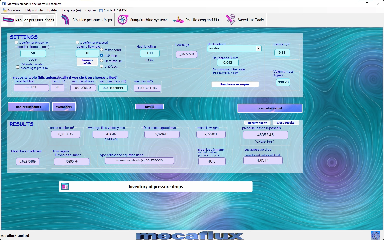
To calculate the energy losses, certain information is required, enter the information in the "Parameters area"
- Pipe diameter (or equivalent diameter if the cross section is not round) mm.
- Flow in the selected unit.
- Length of the pipe in meters
- Select a fluid And in the viscosity chart , select a température
- Select a pipe material
- You may be offered a choice of two equations, the results are similar, but you can compare different methods of calculation.
- You may be offered a choice between two flow regimes when you are close to the limits of transition between laminar and turbulent flow.. This transition is often brought into reality by defects in roughness. (if you restart the calculation by slightly modifying the roughness you switch to a regime or another)
- the pressure drops are given in fluid heights (in meters) and pascals.
- the section of the conduit in m²
- the average fluid velocity in ms
- the maximum flow velocity in ms
- the coefficient of head loss (dimensionless coefficient )
- flow type
- Equation used
- Reynolds number
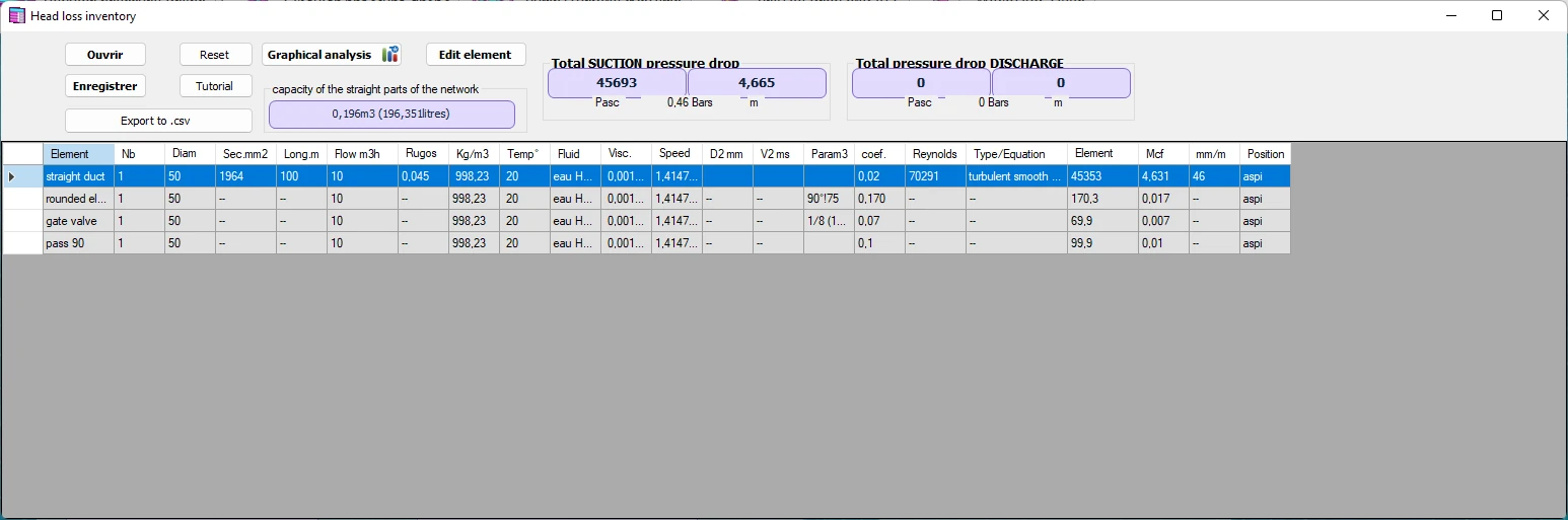
See also: Sizing a hydraulic line or aeraulic according to its flow
Frequently asked questions
What is the difference between major and minor head losses?
Major losses are due to friction along straight pipes and are proportional to their length. Minor losses are due to the fittings of the network (bends, valves, tees, changes of section, inlets and outlets) and are calculated with ΔH = ζ V²/(2g), with a coefficient ζ specific to each fitting (0.2 to 0.3 for a bend, 0.5 for a sharp inlet, 2 to 10 for a partly open valve). The total head loss of the network is the sum of both; in a long, simple network the major losses dominate, in a compact boiler room the minor ones do.
How does the head loss vary with flow rate and diameter?
Roughly as the square of the flow rate: in the DN 50 of the example, 5 m³/h lose 0.95 m, 10 m³/h 3.43 m and 20 m³/h 12.7 m (×3.7 when the flow rate doubles, λ decreasing slightly with the Reynolds number). And as the inverse of the fifth power of the diameter: going from DN 40 to DN 50 divides the loss by 3.3 for the same flow rate. That is why a slightly larger diameter reduces the pumping consumption so much, and why the velocity in water pipes is limited to 1 or 2 m/s.
What head loss per metre should I aim for, and how do I convert metres into pascals?
In hydraulics, 15 mm of water column per metre of pipe (0.15 bar per 100 m) is commonly taken as the compromise between pipe cost and pumping cost, 20 mm/m at most to avoid noise; in air handling, about 1 Pa/m in ducts. To convert, ΔP = ρ g ΔH: 3.43 m of water make 3.43 × 998 × 9.81 = 33,600 Pa. Beware, a loss in metres of fluid column is not the same pressure for every fluid: 1 m of air (ρ = 1.2 kg/m³) is only 12 Pa.
How do I calculate the major head losses of my own network?
Mecaflux Standard calculates the head loss of each section with 120 fluids and every pipe material, displays velocity, Reynolds number, regime and friction factor λ, and its memo adds up sections of different diameters or materials. For a complete network with its branches, fittings and pumps, Mecaflux Pro3D, as a stand-alone licence, draws the network in 3D and balances it automatically. Mecaflux also carries out the study of your project and delivers the calculation report, or offers training on the software applied to your own network.