Page contents
How do I calculate the average velocity of a fluid in a pipe?
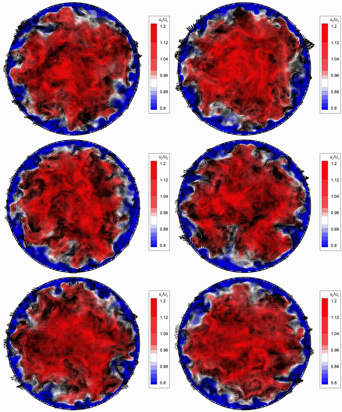
The average velocity is the volume flow rate divided by the flow area: V = Q / S. Inside the pipe the actual velocity varies, zero at the wall and highest at the centre (about twice the average in laminar flow, 1.2 times in turbulent flow); the average velocity is the one used in all calculations: Reynolds number, head losses, continuity equation. Example: 10 m³/h of water (0.00278 m³/s) in a pipe of 50 mm inside diameter (area 0.00196 m²): V = 1.41 m/s. In practice one aims at 1 to 2 m/s for water, or a friction loss below 15 to 20 mm per metre.
Average velocity formula
- V: average velocity, in m/s
- Q: volume flow rate, in m³/s (m³/h ÷ 3,600; L/min ÷ 60,000)
- S: inside cross-section of the pipe, in m²; D: inside diameter, in m (for a rectangular duct, S = a × b)
- The third form gives the diameter to choose for a given flow rate and target velocity
Average velocity and friction loss against diameter, for 10 m³/h of water
| Inside diameter | Area | Average velocity V | Reynolds number | Friction loss |
|---|---|---|---|---|
| 25 mm | 4.9 cm² | 5.66 m/s | 141,000 | 1,610 mm/m |
| 32 mm | 8.0 cm² | 3.45 m/s | 110,000 | 451 mm/m |
| 40 mm | 12.6 cm² | 2.21 m/s | 88,000 | 145 mm/m |
| 50 mm | 19.6 cm² | 1.41 m/s | 70,500 | 47 mm/m |
| 65 mm | 33.2 cm² | 0.84 m/s | 54,200 | 12.7 mm/m |
| 80 mm | 50.3 cm² | 0.55 m/s | 44,000 | 4.6 mm/m |
| 100 mm | 78.5 cm² | 0.35 m/s | 35,200 | 1.5 mm/m |
| 125 mm | 122.7 cm² | 0.23 m/s | 28,200 | 0.5 mm/m |
Detailed explanations and calculation in Mecaflux
In a pipe, friction along the walls slows the fluid , while in the center of the same duct, the fluid is at its maximum speed *.
*maximum speed is calculated as twice the average speed.
We actually find different rates for the same pipe section.
To simplify the calculations we use the average speed:
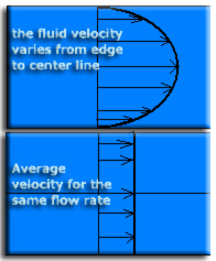
LThe average speed is based on the relationship:
volume flow (m3 / s) / section area (m²) = average velocity (m / s)
The average speed in the case of a constant flow leads to the continuity equation
The maximum velocity of a fluid in a conduit is determined by the pressure loss causes. This head loss "eligible" for the duct is not noisy or does not generate additional cost of operation (energy pumping) must be less than 20 mm / m load per unit length loss.
To correctly sizing the diameter of an hydraulic or aerailic pipe according to its flow rate, you can use the sizing tool: sizing pipe
Interface help choice of pipes according to the flow (incorporated into MECAFLUX standard):
This interface allows to highlight the diameter of ideal conduct for a given flow. We select in the list of usual trade series a series that we wish to test, We then selected the fluid and temperature, in the list of fluids (120 fluids liquids and gases are near to be used with their density and viscosity data).
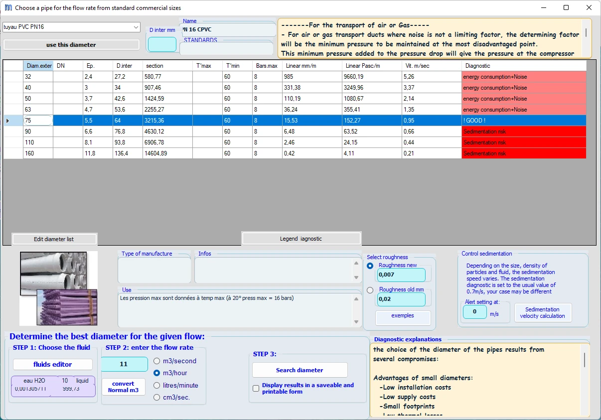
The average speed and speed at the center pipe in Mecaflux Standard:
The minimum velocity of a fluid in a pipe, is often determined by the sedimentation velocity of particles suspended in the fluid. The minimum speed is also determined by the price of the pipes and their installation. Indeed a slow speed brings low operating costs and pumping, but large pipe diameters, ensuring that low speed are expensive to purchase and installation. We consider in practice, that a loss of load per unit length of 15 mm / m, is a good compromise between duct diameter and energy expenditure.
An interface to aid design of aeraulic ducts or hydraulic is integrated mecaflux. So the control of operating / plant cost.
You can choose to enter a speed or flow rate parameter in Mecaflux standard to calculate the Major head loss:
detailed input box mecaflux velocity parameter.
Frequently asked questions
Which velocity should I choose in a water pipe?
From 0.5 to 1.5 m/s at a pump suction (to limit losses and the risk of cavitation), 1 to 3 m/s at the discharge, 1.5 to 2 m/s in a building distribution to stay quiet. For air, 3 to 6 m/s in comfort ducts, 8 to 12 m/s in industrial systems. The other criterion is the friction loss: 15 to 20 mm of water column per metre is a good compromise between diameter and pumping energy.
What is the maximum velocity at the centre of the pipe?
In laminar flow (Re < 2,000) the profile is parabolic and the centreline velocity is exactly twice the average. In turbulent flow the profile is flatter (1/7 power law) and the centreline velocity exceeds the average by only 15 to 25 %. The average velocity remains the reference quantity in head loss formulas.
Why is a minimum velocity also imposed?
To prevent suspended particles from settling (0.6 to 1 m/s for water carrying solids, see settling velocity) and air pockets from collecting at high points. Too low a velocity also means an oversized pipe, expensive to buy and install; the optimum diameter balances installation cost against operating cost.
How do I choose the pipe diameters of my own installation?
The duct sizing tool of Mecaflux Standard shows, for a commercial series (PVC, steel, copper, air duct…), the fluid and the flow rate, the velocity and friction loss of every diameter in the series, and highlights the ideal diameter; you can then enter a velocity or a flow rate in the major head loss tab to detail each run. For a complete network to size or to make more energy-efficient, Mecaflux carries out the study of your project, or offers training on the software applied to your own installation.