
Properly size a pipe or conduit in a hydraulic system or aeraulics, we do small-scale plumbing or study of an industrial network, is a major problem. The distribution of fluids, liquid or gas, air or water, are designed to provide the desired flow rate with minimum cost installation, maintenance and operation.The sound of turbulent fluid in the ducts is also a nuisance to take into account.
Which mean that the pipe dimensions must be accurately studied before.
-
The diameter or the section to be taken into account:
The dimensions of the pipes or tubes of a hydraulic or ventilation network are generally calculated according to the desired flow rate of fluid to transport. The diameter of the pipes is usually the searched dimension. For non-circular ducts, rectangular or oblong section,This allows to calculate the losses, flow or fluid velocities of non-circular ducts as if they were circular.
Interface help choice of pipes according to the flow (incorporated into MECAFLUX standard):
This interface allows to highlight the diameter of ideal conduct for a given flow. We select in the list of usual trade series a series that we wish to test, We then selected the fluid and temperature, in the list of fluids (120 fluids liquids and gases are near to be used with their density and viscosity data).
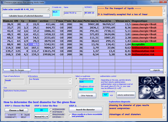
- Diameter influences the speed in ducts and operating costs:
Speed limit subject to a fine, But not too slow...
speed is the determining factor. High fluid velocity causes turbulence within the pipe.
These disturbances are the result of friction on the inner surface of the tube. Suppose (just a moment) be a fluid particle by rafting in conduit. Edges in direct contact with the fluid is more or less "stuck brakes" in the roughness of the pipe. More viscous the fluid is, more the particle stuck against the wall clings to her friends shouting their "wait for me!". While particles are quietly amid the river advancing at full speed. These differences in speed, and the viscosity of the fluid, turn away the particles from the shortest distance (the straight line), and energy that was initially used to get from one point to another is thus wasted in a joyful ballad of friends shouting their joy in the Rockies...
In short, the faster we go, the more it consumes energy and it makes noise. To move the fluid at high speed, so it will take a more powerful pump (more expensive investment) more consuming energy (expensive operation).To reduce the speed (thus energy consumption) without reducing the flow, it is necessary to increase the diameter.Attention to some cases too low speed can be detrimental: When the fluid is charged with heavier particles (suction chips, rainwater ducts...) A minimum speed is necessary for the transport of these particles. Otherwise, they fall to the bottom and pile. If they stick together, the pipe is reduced and may become too narrow for a flow rate increase.(overflow or surge pressure to caps) The minimum transport speed is related to the speed of sédimentation
A disadvantage with larger diameters:PRICE, pipes are more expensive to purchase, transport, laying in space (depth of trench)

Distribution of costs of installation of air distribution.
-
The material, roughness, the purchase price and the cost of the pipe:
the material of the pipe plays a role in the performance of an installation
The roughness of the material given to the purchase evolves over time according to the transported fluid (aggressive oxidant, acid, charged with abrasive material...) and operating conditions (constant water or exposure time to the air oxidant ..) 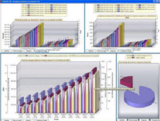
changes in operating costs of an installation according to the flows with the graphical analysis tool mecaflux
Conduct can become a costly roughness in operating energy and see its real price multiply over time.The operating period is compared to the evolution of roughness in the study of the purchase price
Some examples of roughness, depending on the year, and operating conditions- The volume flow rate (speed x section x volume) in m3/h
It is often this specification that is imposed and determines the dimensions of ducts..
For compressible fluids (gas or air):
The gas being compressible, it is possible to change a volume of the same amount of gasby compressing or changing its temperature. It becomes very difficult to speak of a quantity of gas volume without giving the pressure and temperature of the gas when the volume was measured. It would be difficult to give a temperature and pressure whenever we speak of a volume of gas. Then the temperature and pressure at the time of measurement of the volume, are normalized at called normal conditions. This is called normal m3.
Attention, there are two standards, and thus potential errors in conversions:
same pressure of 1013 millibars (average atmospheric pressure) for 2 standards:
DIN 1343 : temperature 273.15K (0°C)
ISO 2533 : temperature 288.15K (15°C)
to know more about Normal meters cubes.htm
For calculations of head loss, the size of volumes of gas (compressed or not) moved into the ducts must be given in cubic meters (m3).
to summarize:
The maximum speed of a fluid in a conduit is thus determined by the pressure loss causes. This pressure drop "eligible" to ensure that the duct is not noisy or does not generate overcost operating (energy and pumping) must be less than 20 mm/m loss of linear load (for liquids).
The minimum speed of a fluid in a conduit is often determined by the sedimentation velocity of the suspended particles in the fluid.The minimum speed is determined by the price, of the pipes and their installation.Indeed a slow speed brings low operating costs and pumping, but large pipe diameters, ensuring that low speed, are expensive to purchase and to installat. We consider in practice, a loss of load per unit length of 15 mm / m, is a good compromise between duct diameter and energy expenditure.
To find a good compromise between the purchase price, installation, operation, pumping, roughness and stock trade, an interface aid design of aeraulics ducts or water is incorporated into mecaflux..
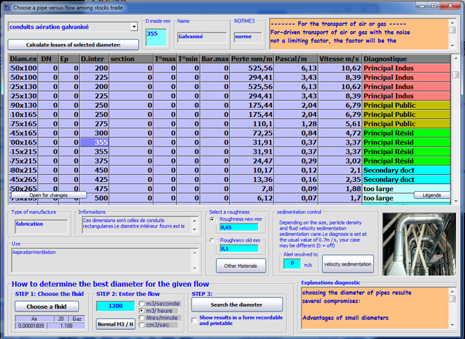
Interface design ducts scans a selected list of pipes and reports the most relevant choice for saving energy and installation costs, depending on the pressure losses caused following the imposed flow. The diagnosis is only fair and the selection may be different depending on the damping strategy or expected operating life. The interesting point is the evolution of the pressure drop as a function of diameter.
See also:
Calculate the flow in a pipe with a vertical drop (gravity flow)