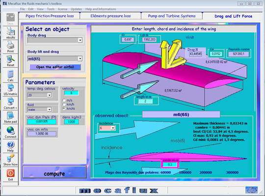
- In aerodynamic or hydrodynamic calculation of lift and drag objects, speed must be entered, that speed is the relative speed. In fluid mechanics the vehicle speed, of the object, or the fluid are considered as the relative velocity between the object and the fluid.
- In a pipe, friction along the walls slows the fluid , while in the center of the same duct, the fluid is at its maximum speed *.
*maximum speed is calculated as twice the average speed.
We actually find different rates for the same pipe section. To simplify the calculations we use the average speed:
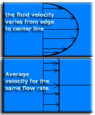
volume flow (m3 / s) / section area (m²) = average velocity (m / s)
The average speed in the case of a constant flow leads to the continuity equation
The maximum velocity of a fluid in a conduit is determined by the pressure loss causes. This head loss "eligible" for the duct is not noisy or does not generate additional cost of operation (energy pumping) must be less than 20 mm / m load per unit length loss.
To correctly sizing the diameter of an hydraulic or aerailic pipe according to its flow rate, you can use the sizing tool: sizing pipe
he average speed and speed at the center pipe in Mecaflux Standard: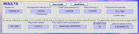
The minimum velocity of a fluid in a pipe, is often determined by the sedimentation velocity of particles suspended in the fluid. The minimum speed is also determined by the price of the pipes and their installation. Indeed a slow speed brings low operating costs and pumping, but large pipe diameters, ensuring that low speed are expensive to purchase and installation. We consider in practice, that a loss of load per unit length of 15 mm / m, is a good compromise between duct diameter and energy expenditure.
An interface to aid design of aeraulic ducts or hydraulic is integrated mecaflux. So the control of operating / plant cost.
You can choose to enter a speed or flow rate parameter in Mecaflux standard to calculate the Major head loss:
 detailed input box mecaflux velocity parameter.