Page contents
What is the polar of an aerofoil and how do I read its lift-to-drag ratio?
The polar of an aerofoil is the curve relating its lift coefficient CL to its drag coefficient CD, each point corresponding to an angle of attack, for a given Reynolds number. It condenses everything needed to use the section: the lift slope (about 0.1 per degree), the maximum CL and the stall angle, the minimum CD and the lift-to-drag ratio CL/CD, whose maximum is the point where the section lifts most for the least drag; the tangent drawn from the origin to the polar gives that maximum. Example: a NACA 0012 at Re ≈ 10⁶ reaches a lift-to-drag ratio of about 75 near 8° of incidence (CL 0.86, CD 0.0115), then stalls around 14 to 15° with a maximum CL close to 1.25. The polar depends on the Reynolds number: at Re = 10⁵ the same shape does not exceed a ratio of about 35.
Formulas of the polar coefficients
- FL, FD: lift (perpendicular to the flow) and drag (along the flow), in N
- ρ: density of the fluid, in kg/m³ (air 1.225, water 1,000); V: relative velocity of the fluid, in m/s
- S: reference area, in m²: chord × span for a wing
- CL, CD: dimensionless coefficients, read on the polar at the angle of attack considered
- Re: Reynolds number based on the chord c (in m), ν kinematic viscosity in m²/s; the polar changes with it
Polar of a NACA 0012 aerofoil at Re ≈ 10⁶
| Angle of attack | CL | CD | L/D = CL / CD |
|---|---|---|---|
| 0° | 0 | 0.0065 | 0 |
| 2° | 0.22 | 0.0070 | 31 |
| 4° | 0.44 | 0.0080 | 55 |
| 6° | 0.66 | 0.0095 | 69 |
| 8° | 0.86 | 0.0115 | 75 |
| 10° | 1.03 | 0.0145 | 71 |
| 12° | 1.15 | 0.019 | 61 |
| 14° | 1.22 | 0.028 | 44 |
| 16° (stalled) | ≈ 1.05 | ≈ 0.07 | ≈ 15 |
Influence of the Reynolds number on the NACA 0012 polar
| Reynolds number | Minimum CD | Maximum CL | Maximum L/D |
|---|---|---|---|
| 10⁵ | ≈ 0.014 | ≈ 0.9 | ≈ 35 |
| 2 × 10⁵ | ≈ 0.011 | ≈ 1.0 | ≈ 45 |
| 5 × 10⁵ | ≈ 0.008 | ≈ 1.1 | ≈ 60 |
| 10⁶ | ≈ 0.0065 | ≈ 1.25 | ≈ 75 |
| 3 × 10⁶ | ≈ 0.0055 | ≈ 1.4 | ≈ 90 |
Detailed explanations and calculation in Mecaflux
Polar of an hydrodynamic aerodynamic profile according to the Reynolds number and incidence or attack angle
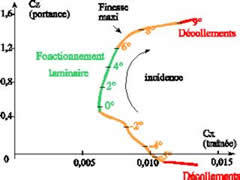
the polar highlights the profiles Lift/Drag ratio.
Databases provides the profiles Cl and Cd (Lift and Drag coefficients) the Lift/Drag ratio = Cl/ Cd ratio. ex: a wing with a Lift/Drag of 40, has lift 40 times higher than its drag.
the study of the polar of a profile, allows to select it considering its Lift/Drag ratio
Polar for hundreds of profiles are stored in databases such as the NACA airfoils database
Polar profiles, selected from the MECAFLUX standard software are reset each change of incidence (or attack angle), depending on the calculated Reynolds number.
The database profiles MECAFLUX Heliciel, allows you to create the new design patterns and memorize the performance under a wide range of Reynolds numbers to create propellers or wings: Interactive profiles polar database Heliciel: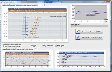
Frequently asked questions
How do I read the maximum lift-to-drag ratio on a polar?
On the CL versus CD graph, draw the straight line from the origin tangent to the curve: the point of contact is the angle of best lift-to-drag ratio, and the slope of the line is that ratio. On a polar plotted against angle of attack, simply look for the maximum of CL/CD, generally between 4 and 8° for a conventional section, well before the maximum CL.
Why does the polar depend on the Reynolds number?
Because the behaviour of the boundary layer changes with it. At low Reynolds numbers (small chords, low speeds: models, small propellers, drones), the boundary layer stays laminar and separates easily: higher drag, early stall, reduced lift-to-drag ratio. At high Reynolds numbers it becomes turbulent and resists separation better. A section chosen from a polar measured at Re = 3 × 10⁶ can disappoint on a propeller working at 10⁵.
What is the difference between the polar of a section and that of a wing?
The polar of the section is measured in two-dimensional flow (infinite span). A real wing of aspect ratio λ adds an induced drag CL²/(π λ) and has a lower lift slope: a wing of aspect ratio 6 has a maximum lift-to-drag ratio of about 20, where its section shows 75. The polar of the wing is derived from that of the section by adding this term, which is what wing and propeller design software does.
How do I obtain the polar of the section of my own wing, fin or propeller?
Mecaflux Standard offers 11 sections in the drag and lift tab: for the chosen chord, speed and fluid, it recomputes the polar at the actual Reynolds number at each change of incidence and displays lift, drag and lift-to-drag ratio in physical values. Heliciel goes further with its database of hundreds of sections, stores their polars over a wide range of Reynolds numbers, lets you draw your own sections and applies them element by element to a wing or propeller in 3D. For a wing, foil or propeller project, Mecaflux carries out the study of your project, or offers training on the software applied to your own case.