See also: calculate the flow in a hydraulic or aeraulic duct system with mecaflux Pro 3D
If the ducts are not of circular section (rectangular or oblong-type aeration or ventilation), the diameter used is the equivalent diameter, or the hydraulic diameter
Example of calculation of losses in the pipes of a network:
display the diagram in a window
For this scheme the fluid network is computable in three straight parts :
- a portion combining 11.5 meters diameter circular section 40 mm-
- a portion 2 meters in diameter circular section 80 mm
- a portion 6.5 meters oblong section width 140 mm and height 80 mm
Detailed procedure rectilinear part 1:
Select the tab major regular head loss and enter:
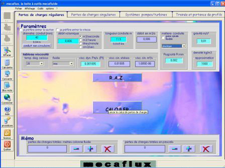
1 - the diameter :40 mm
2 - the flow : 0.006 m3/sec
3 - the length of pipe:11,5 mètres
4 - :material: plastic (the proposed roughness can be changed)
5 - density (default) water :1000Kg/m3
6 - the fluid and temperature: water 20°C
7 - gravity ( 9.81m/s²)
- Click calculate the results sheet appears:
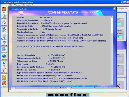
-Record your results in a file by clicking on Register in the toolbar (you are invited to add your file to an existing file, click no and create a file example1). it is advisable to save all your results on the same network in the same file..
-Close the "results sheet" window, the results are displayed in the inventory of head loss.
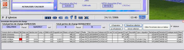
- In the inventory you can add successive results you will now calculate:
- For the straight sections 2 and 3, perform Part 1 (data change erases previous results)
- for the part 3 click on "non-circular section" and enter the height and width of the duct for the equivalent diameter of the oblong section
The results of calculations are in inventory
now proceed to the singular pressure minor head loss caused by the accidents on path:
following: losses in the valve and elbows