Page contents
What is a hydraulic diagram and how is it used for head loss calculation?
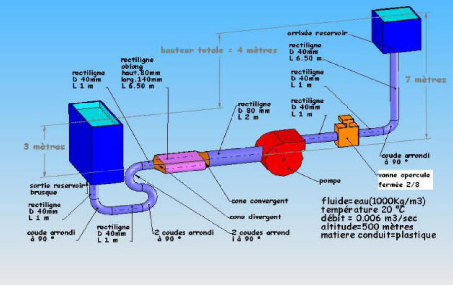
A hydraulic (or ventilation) diagram represents a fluid network element by element: tanks, pump or fan, pipes with their lengths and diameters, fittings (elbows, valves, filters, strainers, check valves) and elevations. It is the starting point of the calculation: each element of the diagram becomes a line of the head loss inventory, and the sum of the losses along the most unfavourable path, added to the elevation difference and to the outlet dynamic pressure, gives the head the pump must supply at the required flow rate.
From the diagram to the pump head
- Hpump: total head required from the pump, in m of fluid (ΔP = ρ g H)
- Δz: elevation difference between the suction tank surface and the outlet, in m
- P2 − P1: pressure difference between the outlet tank and the inlet tank, in Pa (0 if both are open to the atmosphere)
- λ L / D: major losses of each straight pipe; ζ: minor loss coefficients of each fitting
- V: velocity in each element, in m/s; Voutlet² / 2 g: dynamic pressure at the outlet, in m; g = 9.81 m/s²
Inventory example for a simple pumping system
| Diagram element | Data | Loss or head | In metres of water |
|---|---|---|---|
| Straight pipes | 45 m, DN 65 | 23,700 Pa | 2.42 m |
| Strainer and foot valve | ζ = 2 + 2 | 6,530 Pa | 0.67 m |
| 4 elbows 90° and 1 open valve | ζ = 4 × 0.3 + 0.2 | 2,280 Pa | 0.23 m |
| Static elevation | −3 m + 7 m = 4 m | 39,160 Pa | 4.00 m |
| Outlet dynamic pressure | V = 1.81 m/s | 1,630 Pa | 0.17 m |
| Total head required from the pump | at 6 L/s | 73,300 Pa (0.73 bar) | 7.49 m |
Detailed explanations and calculation in Mecaflux
This hydraulic diagram (below) provides support, tutorials calculation pressure losses with the software Mecaflux standard.
Mecaflux standard do not produce this type of schemes, to produce hydraulic diagrams, ventilation or other fluid systems in 3D, use Mecaflux Pro 3D software. (see didacticiel Pro 3D)
Frequently asked questions
Which elements should appear on a hydraulic diagram used for calculation?
Everything that creates a head loss or a head: each straight pipe with its length, inside diameter and material (roughness), each fitting (elbow, tee, reducer, valve, filter, strainer, check valve, meter), the elevations of the free surfaces and of the outlet, the pressures of closed tanks, and the flow rate required in each branch.
How do I go from the diagram to the head loss inventory?
Follow the most unfavourable path (the longest or the highest) from the suction to the outlet and compute the loss of each element at the operating flow. In Mecaflux Standard, each element of the diagram is entered in the head loss inventory, which adds up the losses, plots the system curve and finds the operating point with the chosen pump. The other branches are balanced with valves.
What is the difference between an open and a closed system?
A closed system (heating loop, cooling circuit) returns to its starting point: the elevation and the outlet dynamic pressure cancel out and the pump only overcomes the head losses. An open system (pumping from one tank to another, irrigation) adds the elevation, the pressure difference between tanks and the outlet dynamic pressure.
How do I get my network calculated from my diagram?
With Mecaflux Standard, you enter the elements of the diagram in the head loss inventory and get the system curve and the pump operating point; with Mecaflux Pro3D, you draw the network in 3D, branches and loops included. If you prefer to entrust the calculation, Mecaflux carries out the study of your project from your diagram and delivers the calculation report with the software file, or offers training on the software applied to your own network.