
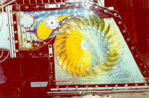
You can estimate the recoverable energy by a turbine instalation with Mecaflux software and design a Kaplan turbine type, propeller or tidal with Heliciel software.
Comparative efficiency of types of turbines
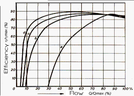
a: propellers b: ![]() Turbine Francis
Turbine Francis
c: ![]() Turbine
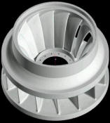
Kaplan (propeller) d:
Turbine
Kaplan (propeller) d: ![]() Turbine Pelton
Turbine Pelton

Flow 4 - 15 m3/s
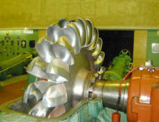
This type of turbine is particularly suitable for high head applications with variable flow, its efficiency is not very sensitive to the variation. Small Pelton turbines can achieve mechanical efficiency (to the shaft) of 90%.Turbine Francis (1868)
Drop height: 10 - 700 mètres
Flow 4 - 55 m3/s
Like Kaplan turbine, the Francis is a reaction machine. The wheel is immersed and operates both the water velocity (kinetic energy), that a pressure difference.
This type of turbine is located in the old low-head installations (less than10 m) where they are generally in water chamber, ie without scrollcase. Their speeds are very slow and their adaptability to changes in flow rate is relatively low, they were replaced by small Kaplan, entered the market in the years 1930-1940.
Currently, the field of use of Francis is ideally located between 20 et 100 m. For heads, above 60 m, they are preferred to Pelton when the flow is important.
The mechanical performance of small Francis from developments in the laboratory is of the order of 92%
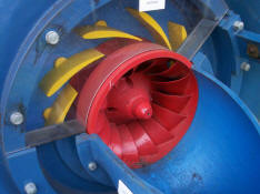
turbine Kaplan propeller (1912) Drop height: 0 - 30 meters Flow 1 - 350 m3/s The axial turbines include the Kaplan, bulbs and propeller turbines (reaction). The Kaplan turbine is a propeller turbine, with moving blades. Cela permet un meilleur fonctionnement de la turbine sur une plus grande gamme de débits. This allows a better functioning of the turbine over a wide range of flow rates. Their level of mechanical efficiency of about 92% in small hydroelectricTo deepen the understanding of turbine KAPLAN, turbine propeller or tidal turbine, all information are on the partner site mecaflux about the study of turbines: heliciel.com hydraulic turbines on heliciel.com:
an original turbine : |
turbine Banki(1903)
Assess the recoverable energy by a turbine with the software Mecaflux standard:
A turbine is chosen based on the flow rate and pressure available, the drop height with flow pressure range given above. You can easily assess for relations between power, pressure, flow rate, drop height, pressure drop... with mecaflux in pumps and turbines tab. The losses in the penstock will be calculated and included in the evaluation of the deliverable power. The turbine efficiency should be entered according to the manufacturer datas.
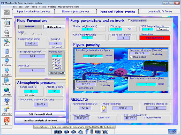
the pumps and turbines tab in MECAFLUX Standard
The turbine's efficiency is related to its design, to design a Kaplan turbine, propeller or tidal turbine use the partner site: Heliciel.com:
- kaplan hydraulic turbine energy capture 1/3:Components Overview
- kaplan hydraulic turbine energy capture 2/3 :guide vanes + turbine
- kaplan hydraulic turbine energy capture 3/3 :design method
- Tutorial hydroelectric turbine design 1/3 :Site power and turbine design
- Tutorial hydroelectric turbine design 2/3 :Design :guide vanes or stator
- Tutorial hydroelectric turbine design 3/3 :Choice sections, design draft tube
Building a turbine propeller, Kaplan, tidal turbine, and wind with HELICIEL (PROP calculation software):
The design of propeller turbines is finally within reach of all contractors with this propeller design software. Just know the flow to assess the power that will be supplied to the propeller shaft. A database performance profiles is integrated in the software, and optimization functions are used to define the best speeds, depending on the types of blades that you draw. The pitch and the optimum twisting of the blades is calculated and simulated pitch variation can be done ....
You will find the Heliciel site, a method of mini-hydropower plant design, complete, allowing the design and performance estimation and dimensional parameters of the propeller or Kaplan turbine , from guide vanes to draft tube. This method of detailed design, is followed by a complete tutorial for the 3D modeling of the turbine blades, and distributor. The igs format enables the transfer of blades 3D files, on a CAD to complete the assembly with other elements ...
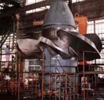
Study and design of the blades of a Kaplan turbine with Héliciel software
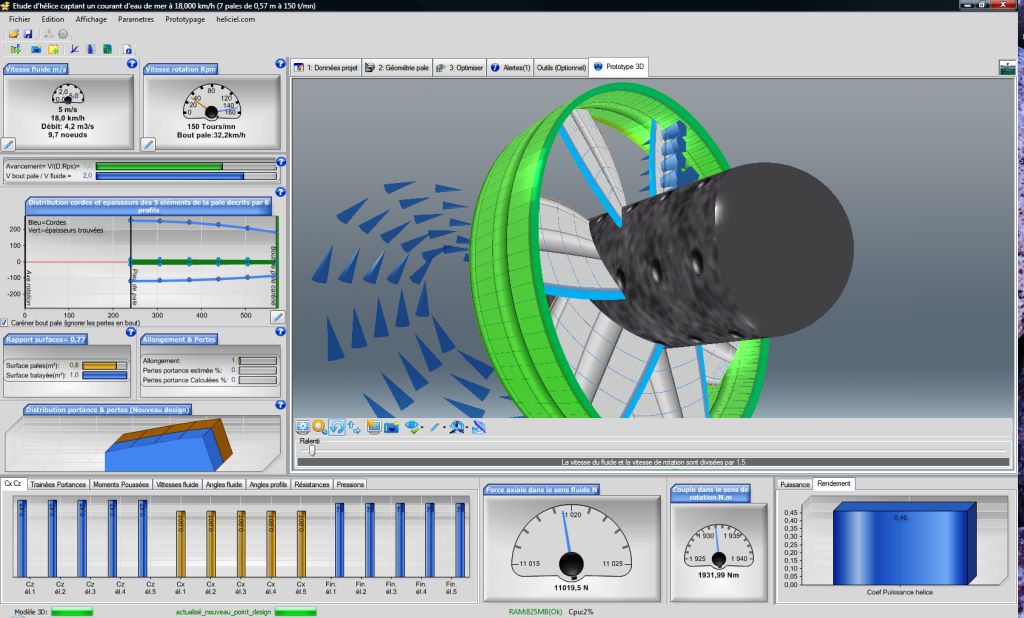
Heliciel est un logiciel permettant la création de turbines HELICE , car il permet de dessiner et construire des pales et de calculer le rendement d'une hélice de captage d'énergie hydraulique du style Kaplan,a bulbe, ou des hydroliennes mais aussi des hélices avions bateaux ventilateurs....
Heliciel is software for creating turbines PROPELLER, it allows you to draw and build blades and calculate the efficiency of a Kaplan or propeller hydraulic turbine, bulbous, or tidal turbines, but also aircraft or boats propellers, fans ....
The turbine of a hydroelectric facility will be effective only if the hydroelectric energy is properly channeled. The hydroelectric power at the input of the turbine is dependent on the pressure drop and travel speeds in the organs of the system. We will see an example of how the captured energy varies, depending on the parameters of a penstock for the same drop height and flow available ...
Example of calculating a hydroelectric facility with a Pelton turbine in software Mecaflux Pro3D:

A pressure pipe (penstock) collects a water intake in a dam. This water intake from gravity, has an output flow which is conditioned by :
- the head losses,
- the height between the water intake and the outlet pipe,
- and the speed to at the outlet line (dynamic pressure).
the gravity flow operation is established when: load losses + dynamic pressure is equal to the Vertical drop. .
The drop is a motive power, as long as this energy is higher, the load losses + dynamic pressure at the outlet, fluid accelerates until the pressure drops + dynamic pressure at the outlet use all this energy...
A Pelton turbine collects the dynamic pressure energy at the outlet pipe. the dynamic pressure should therefore be maximum. It is necessary to avoid consuming of energy in head loss, and transform the maximum amount of energy, in dynamics pressure at the exit point.
In Pelton turbines, an outlet nozzle (cone narrowing) which will accelerate the fluid outlet so as to create the dynamic pressure (speed energy) is placed just where this is useful (in the jet striking the buckets of the turbine)
If the network creates speed in its ducts so that the speed should be outputted .... (diameter too small and lack of shrinking output.) The energy will be consumed in losses, it is necessary that the velocity of the fluid is as small as possible in the pipes.
overall:
- the flow of gravity operation is established when: load losses + dynamic pressure is equal to the elevation
- distribution losses (energy lost) <=> dynamic pressure (recoverable by the buckets of the turbine energy) is the heart of the problem.
- To have a good system requires a maximum dynamic pressure output for a minimum of head losses.
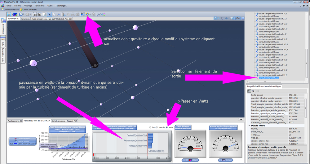
To know the available energy at the outlet system, with Mecaflux Pro3D, After updating the flow by clicking "locate intake gravity water", click on the output (outlet tube) to select it, and, in the result field (check results in Watts) you get a dynamic pressure. It is this energy that should be recovered in large part by the buckets of the Pelton (- turbine efficiency)
To illustrate these remarks, An example of a collection from three configurations with a flow rate of 190 m3 / h and an altitude to about 625 meters, for a Pelton turbine:
Pelton turbine configuration 1:Result with an exit without nozzles, dynamic pressure output is 500 watts for a flow rate of 192 m3 / h. The Pelton turbine will receive an energy of 500 Watts, the head losses are large (300 Kw)
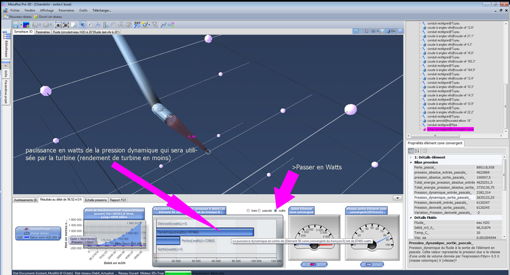
Pelton turbine configuration 2: In this configuration (below) nozzle was just added at pipe outlet: the dynamic pressure at the outlet rose to 97 Kw for a flow rate of 96 m3/h. The Pelton turbine will receive an energy of 97 kWatts , loss of overall expenses are approximately (66 Kw) ,the gravity flow is small compared to the available flow (190 m3/h), It should increase the flow ..
Pelton turbine configuration 3: In this configuration (see below) on a 4 nozzle pipe outlet, the flow rate is increased: the dynamic pressure at the outlet of a nozzle is 37 Kw, this gives 37*4=148 Kw. The Pelton turbine will receive a kinetic power of 148 kWatts :
This simple and quick example here is ending, but the pressure losses are still high (253 Kw) to improve the system, increase the diameter of the pipe to reduce the pressure losses. We will also check the change in pressure in the pipe to prevent cavitation...
List of Manufacturers study desk, turbine wheel...
If you are manufacturer of turbines and want to appear here, please send an email to __contact@mecaflux.com___
https://www.somipp-turbine87.fr/index.html
https://modelagedechartreuse.monsite.wanadoo.fr/index.jhtml
https://www.viry.com/micro_centrales_hydrauliques.htm
https://perso.orange.fr/energies-nouvelles-entreprises/ch15-1.htm