The aerodynamic or hydrodynamic lift is a force perpendicular to the movement of the fluid. It is created by the suction in a negative pressure zone, formed on top of the profile designed for this purpose. It depends on the displaced mass of fluid.
The lift is calculated according :
- A coefficient measured in a wind tunnel called Cl or lift coefficient
- The wing area (in the case of the lift is not the miship who serves as a calculation reference)
- Speed of the flow or wing
- Density of fluid passed through
Cz or lift coefficient is measured in a wind tunnel and there are databases available for many profiles, which provide performance at different speeds and different incidences.
lthe lift is in general necessary to fly the wing with its load strength. It is linked to the drag which will be compensated by a thrust at least equal to take off
In the case of profiles measured in the wind tunnel, the lift is calculated according to wing surface.
![]()
- Lift in Newtons
- CL is the lift coefficient, it is determined experimentally in a wind tunnel or with numerical methods
- p is the density of the fluid KG/m3
- S wing surface m²
- v relative velocity of the fluid m/s
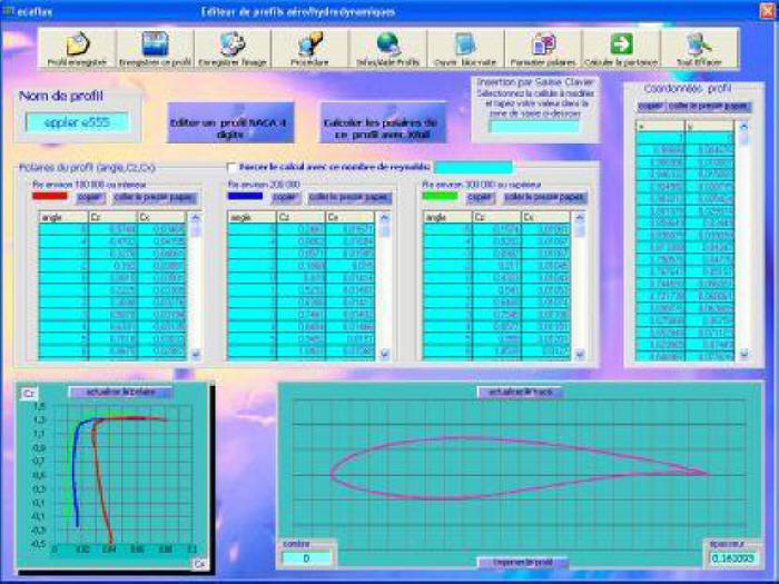
In his profile editor, Mecaflux Standard integrates Xfoil to determine profiles lift and drag
The explanation of the phenomenon of aerodynamic or hydrodynamic lift can be partly given, by the variation of the fluid speed , between the lower and upper surfaces.This change in speed causes a change in pressure (see Bernoulli) that generates lift.
In this animations below, of the fluid path around a cylinder and around a profile, you can see the difference in speed generated for :
A profile of zero lift incidence, and a fixed cylinder: equivalent fluid path between the lower and upper surfaces => no pressure difference=>no lift
Below is a profile with incidence and a rotating cylinder: longer fluid path on the underside than on the upper surface=> difference in speed=>pressure difference=> Lift
The rotation of the cylinder causes an overspeed on top of the cylinder, the speed increase creates a vacuum within the fluid, which causes the lift.
This approach is very simplified to deepen the theory of lift, see : Lifting line theory on Heliciel.com
The Mecaflux standard software offers 11 different profiles to 8 angles of incidence and 3 ranges of Reynolds numbers and extrapolations
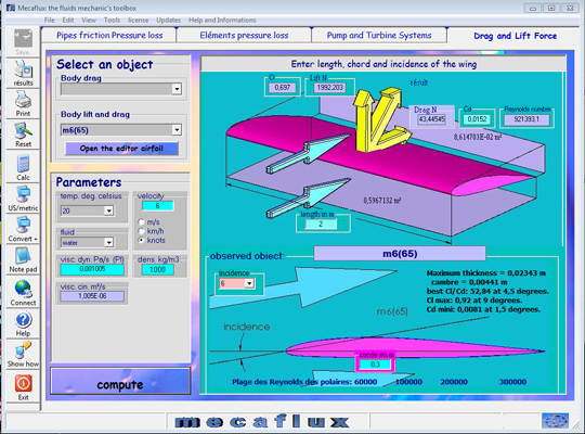
If that is not enough you have a profile editor allows you to build your profile files and integrate them into the calculation of lift
See also: create the wing 3D file