-
hydraulic head loss through valve, elbows, inlet and outlet tanks ...
show the scheme of the sample in a window
Detailed procedure for calculating losses in the gate valve, closed 1/8: - Select the tab elements pressure losses (minor head loss) and choose among the elements of piping the valve gate.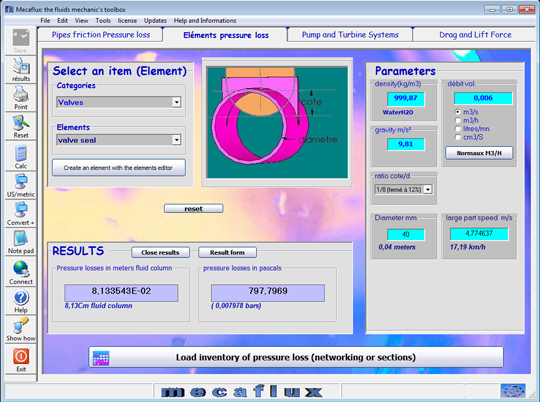
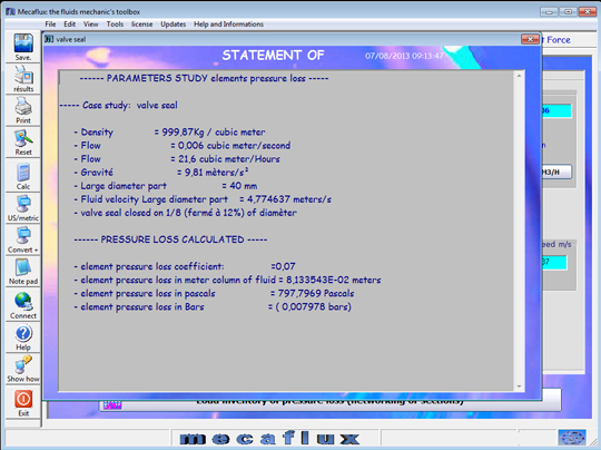
- - Density: 999.87 kg/m3 (water at 0 degrees)
- - Gravity: 9.81 m / s ² (default)
- - Flow: 0006 m3 / s
- - Diameter: 40 mm
- - The closing ratio / diameter: 1/8
- - Click on calculate
- Your results are also accumulated in the inventory load losses: Note that the head loss inventory, retains and accumulates the calculated values of the pipes friction pressure losses tab (major head loss) , and element losses tab (minor head loss)
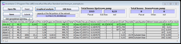
- After calculation you should accumulate (92739 pascals) in the inventory of losses
back to exemple internals flow
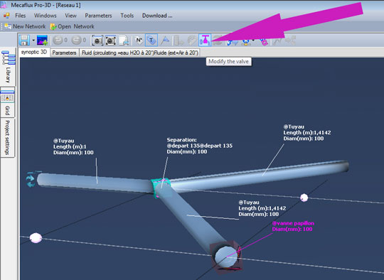
With mecaflux Pro3D, It is very simple to insert a valve on each branch to control the flow in the branch:
- Select the conduct on which to insert the valve and right click to open the context menu:

- Choose the type of valve and its degree of closure and click insert:
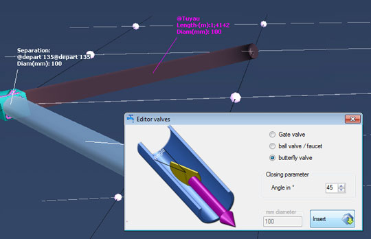
- If you want to change the degree of closure of the valve, the valve selected, this button activates the control valves, and gives you access to its modification: