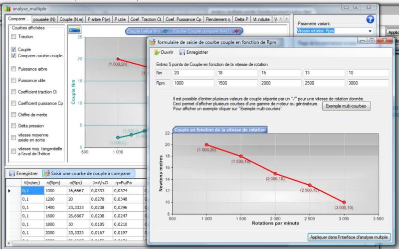
The Operating point of a turbine, is defined by the rotational speed and the fluid velocity. The propeller turbine must have an optimized twist to its operating point. The optimization of the propeller turbine through the analysis of its performance at different operating points.
For a propeller turbine, converting the energy of a fluid stream in torque on a shaft, the actual speed, of the energy capture propeller, will be the speed that balance:
- The motor torque generated by the propeller during passage of fluid into its blades,
- and the resistive torque produced by the generator, which is connected the propeller.
input torque curve:
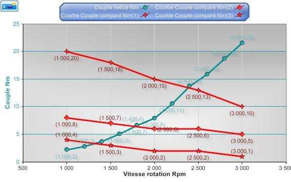
- the propeller mounted on the engine whose torque is described by curve 1 operate at 1300 rpm
- the propeller mounted on the engine whose torque is described by curve 1 operate at 1750 rpm
- the propeller mounted on the engine whose torque is described by curve 1 operate at 2400 rpm
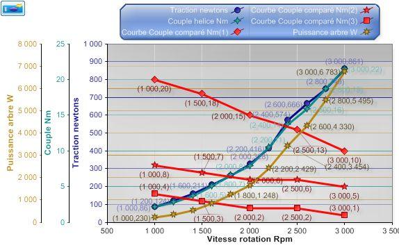
- the propeller mounted on the engine, whose torque is described by the curve 1, will provide a thrust of 150 newton at 1300 rpm and a shaft power of about 300 watts
- the propeller mounted on the engine, whose torque is described by the curve 2, will provide a thrust of 250 newton at 1750 rpm and a shaft power of about 1200 watts
- the propeller mounted on the engine, whose torque is described by the curve 3, will provide a thrust of 550 newton at 2400 rpm and a shaft power of about 3400 watts
Of course these values are valid only if the propeller has a strength appropriate to the calculated thrust, and that cavitation does not spray fluid. We must therefore control these parameters, at speeds of rotations found!