
The pumps are the machines which perform the flow of a fluid (liquid or gas) in a network using a certain amount of energy supplied by a motor.
The characteristics of flow and pressure of the pump, determine a curve of pump operation, which should be compared with the pressure drop and the slope of the network. The comparison of the pump curve and the system curve allows you to find an operating point of the network pump system. If the pumped fluid is a liquid, the cavitation of the suction duct, or the pump, must be controlled.
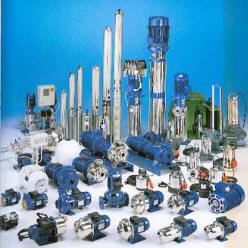
There are many types of pumps classified into two types: volumetric pumps and turbo pumps:
1: The volumetric pumps: have a field of application of pressure up to 10 000 bar and flows from 0.1 to 10 m3 / h. They can be rotary or alternative, they can be applied to liquids and gases (compressors and blowers) they can generate high pressures:
| Examples of alternative volumetric pumps: | Examples of rotary volumetric pumps: |
|---|---|
Diaphragm :
|
Lobe:
|
Piston:
|
pallets:
|
Piston line:
|
gear:
|
Piston in Star:
|
screw:
|
rotary plate pumps fixed flow:
|
peristaltic:
|
rotary plate pumps variable flow:
|
Grains: |
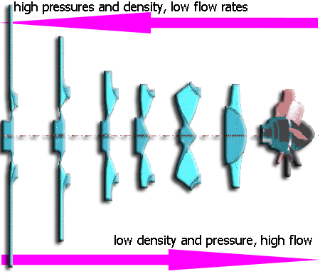
2: The turbo pumps: they have a scope of pressures from 0.6 to 20 bar and flow rates up to 50 00 m3 / h. Les turbopompes peuvent etre axiales (helices) radiales (centrifuges) ou les deux àla fois (helicocentrifuges) , elles peuvent s'appliquer aux liquides et aux gaz ( compresseurs soufflantes ventilateurs).
Types of turbo pumps are related to flow, the fluid density and pressure to generate to achieve throughput specifications.
Radial centrifugal pumps:  |
mixed flow pumps:
|
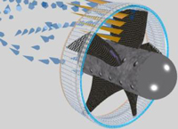
| axial compressor:
|
To size and calculate the operating point of a pump correctly, we must know the parameters the network to which is intended the pump. these parameters are:
- -The volume flow m3 / s
- -The saturation vapor pressure of the fluid if it is a liquid (used to assess the risk of cavitation).
- -Suction height. (If liquid)
- -Discharge head. (If liquid)
- -Pressure or depression sucked reservoir
- -Pressure or depression discharge reservoir
- -The pressure head loss at suction and discharge "major head loss" and "minor head loss"
- -the performance of the pump (for calculations of energy consumption and engine power)
- -The NPSH of your pump. (Assesses the risk of cavitation)
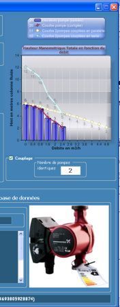
Example curve total head (hmt) of a pump according to the flow:
- See other curves and caracteristics pump: The pump operating point
Calculate the operating point of a pump, and sizing the network pump, depending on the pressure losses in the network with Mecaflux standard:
-
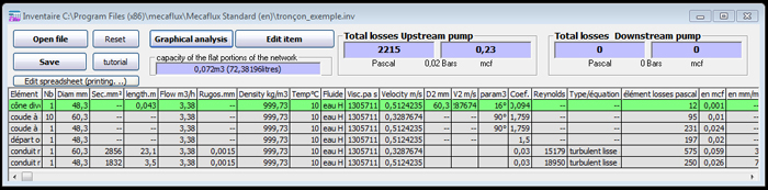
-you calculated head loss of the different elements of your most disadvantaged sections (other sections must beings equipped with valves or other accessories to balance the head loss).
-
-you saved your network losses inventory
-
-you have already entered the pump curves in the editor pump, or you enter a curve (6 points in height depending on flow rates)
In the inventory of losses, click graphical analysis,
- if you want to test an inventory section that you have previously registered, click on load a network (in interface graphical analysis).
- If your network is open select Open Network and enter the height of the load and the section of the output element otherwise select closed network.
You are near to launch the search for the operating points of your pump according to the losses of the network and selected in the editor (or entered as curve) pump.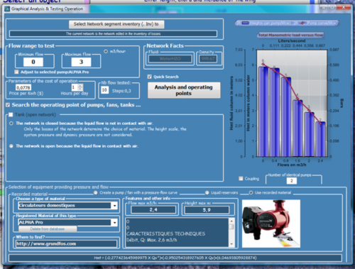
- You can check the "Quick Search" to display only the operating points of the pump according to the network in miniature and move quickly from one pump to another with your editor to start several tests:
- or launch a full analysis also testing the coupling configurations
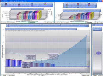
Operating points of the pump coupled in parallel or in series, or alone.
Example curves height gauge, depending on the flow of pumps connected in parallel or in series, in the editor pumps mecaflux
Control the risk of cavitation, and calculate the power of the pump at a given flow rate with Mecaflux Standard:
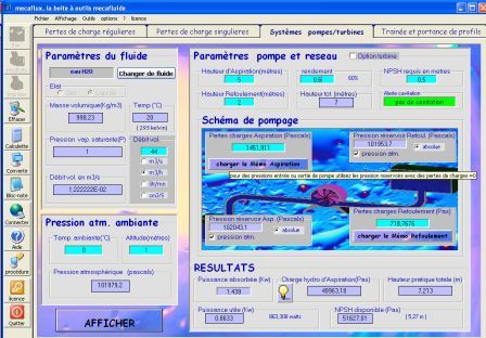
In this tab you can study the parameters of pumps and turbines
-
-Enter the network throughput:0,006m3/sec (if you following the exemple hydraulic network)
-
-Select the fluid water at 20 degrees (this determines the saturation vapor pressure and density)
-
-Enter the ambient temperature and altitude
- -Enter the suction head Attention in this scheme exemple, the pump is below the suction reservoir (In charge pump, the fluid descends) so we must enter a negative height:-3 mètres (the tooltip associated with the text box tells you)
This deserves some explanation: for signs of height, we must think about the pump and the effort it must provide to circulate the fluid:
- descending = negative sign
- up = positive sign
- Enter the height of discharge: as the discharge tank is above the pump, the fluid flows upwards,the value is positive : 7 meters
- Entrez soit :
- the efficiency of your pump (0.8 is an average efficiency) to obtain the energy absorbed by the pump shaft in KW. For power consumption of the pump motor must enter a performance including the performance of the electric motor (0.5 is an average efficiency for a pump and motor assembly)
- the input power at the pump shaft (you will obtain the efficiency of your pump body)
- Or the motor output (you will have the performance of the overall "motor and pump body"")
- Click to view the results sheet to see the summary of your network:

In this part of the results sheet, we see that the pump does not Cavitate and consumes 0.99 KW with an efficiency 0.8
Back to exemple internal flow