Page contents
How do I calculate the drag force and the drag coefficient Cd?
Drag is the force a fluid opposes to the motion of a body, along the direction of the flow. It is given by F = ½ × ρ × V² × S × CD: it grows with the square of the relative velocity V, with the density ρ of the fluid (water is 830 times denser than air), with the reference area S and with the drag coefficient CD, measured in a wind tunnel, which expresses the shape of the body: 0.47 for a sphere, 1.17 for a disc facing the flow, 0.04 for a streamlined teardrop body. Example: a 0.1 m sphere in air at 20 °C (ρ = 1.204 kg/m³) at 10 m/s has a frontal area of 78.5 cm² and undergoes F = 0.5 × 1.204 × 10² × 0.00785 × 0.47 = 0.22 N; a 0.5 m disc facing the same wind undergoes 13.8 N. The calculator below gives the drag of common bodies (sphere, cylinder, plate, cube, parachute, streamlined body) with the reference CD matching the Reynolds number, or the lift and drag of a wing.
Drag and drag coefficient formulas
- F: drag force, in N, parallel to the flow and opposed to the motion of the body
- ρ: density of the fluid, in kg/m³ (air at 20 °C: 1.204; water: 998)
- V: velocity of the fluid relative to the body, in m/s; ½ ρ V² is the dynamic pressure, in Pa
- S: reference area, in m²: frontal area for a bluff body, wing area for a wing
- CD: drag coefficient, dimensionless, measured in a wind tunnel for each shape and given against the Reynolds number Re (L reference dimension in m, ν kinematic viscosity in m²/s)
- P: power needed to overcome the drag, in W: it grows with the cube of the velocity
Reference drag coefficients and drag in air at 10 m/s
| Body | CD | Example dimensions | Frontal area S | Drag F at 10 m/s |
|---|---|---|---|---|
| Sphere | 0.47 | diameter 0.1 m | 78.5 cm² | 0.22 N |
| Cylinder across the flow (mast, cable) | 0.63 (L/D = 1) to 1.2 (L/D > 40) | D × L | ||
| Disc facing the flow | 1.17 | diameter 0.5 m | 0.196 m² | 13.8 N |
| Rectangular plate facing the flow | 1.18 (square) to 2.0 (very elongated) | 1 m × 0.5 m | 0.5 m² | 35.5 N |
| Cube facing the flow | 1.05 | side 0.5 m | 0.25 m² | 15.8 N |
| Hollow hemisphere, concave side (parachute) | 1.42 | diameter 5 m | 19.6 m² | 1,679 N |
| Hollow hemisphere, convex side | 0.38 | diameter 0.5 m | 0.196 m² | 4.5 N |
| Streamlined teardrop body (L/D ≈ 3) | 0.04 | diameter 0.3 m | 0.071 m² | 0.17 N |
Dynamic pressure ½ ρ V²: drag per m² of frontal area for CD = 1
| Relative velocity V | In air | In water |
|---|---|---|
| 1 m/s (3.6 km/h) | 0.60 N/m² | 499 N/m² |
| 2 m/s (7.2 km/h) | 2.41 N/m² | 1,997 N/m² |
| 5 m/s (18 km/h) | 15.1 N/m² | 12,480 N/m² |
| 10 m/s (36 km/h) | 60.2 N/m² | 49,900 N/m² |
| 20 m/s (72 km/h) | 241 N/m² | 199,600 N/m² |
| 30 m/s (108 km/h) | 542 N/m² | 449,200 N/m² |
| 50 m/s (180 km/h) | 1,505 N/m² | 1,248,000 N/m² |
Detailed explanations and calculation in Mecaflux
The drag force can be calculated from:
-
called a coefficient Cd (Cd is the drag coefficient, is determined experimentally in a wind tunnel)
- Fluid's speed,
- Fluid's density,
- and the reference surface, which may be different according to the object studied:
- The front surface (projection perpendicular to the flow) if the object is non-profiled, see: Midship area
- Wing area if the object is profiled, see: Wing area
with the drag formula:
p is the density of the fluid KG/m3
S front surface or Wing area m²
v the relative velocity* of the fluid m/s
*whether the fluid, the object, or both moving, we take into account the speed relative to each other..
Cd and Cl (drag and lift coefficient) measured experimentally are in the database, where the value of disks is always given as a function of the Reynolds number, which includes the fluid kinematic viscosity.
Methods or mathematical determination of Cd Cl exist, reaching levels of interesting information. The coefficients of drag and lift are often represented by graphs called Polars.
(In his profile editor mecaflux integrates Xfoil to determine the lift and drag profiles)
The drag force is expressed in Newtons, It is that which resists movement or slows down the ship.
The CD allows us to extrapolate the resistance to progress for a series of geometrically similar profiles. When the drag is studied in water we talk about viscous resistance: Rv and the formula for calculating the coefficient of viscous drag is related to the Reynolds number Re and takes the name of viscous drag coefficient: Cv Rv= Cv . (Re . K/L). rugosity(K) In naval hydrodynamics, sometimes a method method of dual models are used to determine the viscous resistance. With MECAFLUX standard Detail of the interface drag and lift calculation in MECAFLUX standard
The one the CD was measured with, otherwise the coefficient is meaningless. For a bluff body (vehicle, sphere, building, parachute) take the frontal area, that is the projection of the body on a plane perpendicular to the flow; for a wing, a keel or a sail take the wing area, chord × span. Car manufacturers often quote the product S × CD directly, in m², which is all the calculation needs. Yes, through the Reynolds number. For a sphere, CD equals 24/Re at very low speeds (Stokes' law, a settling dust particle), levels off around 0.47 between Re = 10³ and 2 × 10⁵, then drops sharply to about 0.2 beyond 4 × 10⁵: this is the drag crisis, where the boundary layer becomes turbulent and reattaches on the rear of the body. A rough surface (golf ball) brings this crisis forward. The coefficients in the table are those of the subcritical regime, the most common one. First by streamlining it: a teardrop body has a CD of 0.04 against 1.17 for a disc of the same diameter, thirty times less drag, because the low-pressure wake behind the body disappears. Then by reducing the frontal area and the speed, since the force varies as V² and the power as V³: driving at 130 km/h instead of 110 km/h raises the aerodynamic power by 65 %. Finally, on an already streamlined body the remaining drag is mostly skin friction, reduced by a smooth surface finish; on a wing, induced drag is reduced by increasing the aspect ratio. The drag-lift tab of Mecaflux Standard calculates the drag of geometric bodies and the lift and drag of 11 aerofoils, in air, water or any of the 120 fluids of its database, and derives the power to supply at each speed. Heliciel completes the study for a real wing, foil or propeller, computed in 3D element by element with the polars of hundreds of aerofoils. For a vehicle, hull or wing project, Mecaflux carries out the study of your project and delivers the calculation report, or offers training on the software applied to your own case.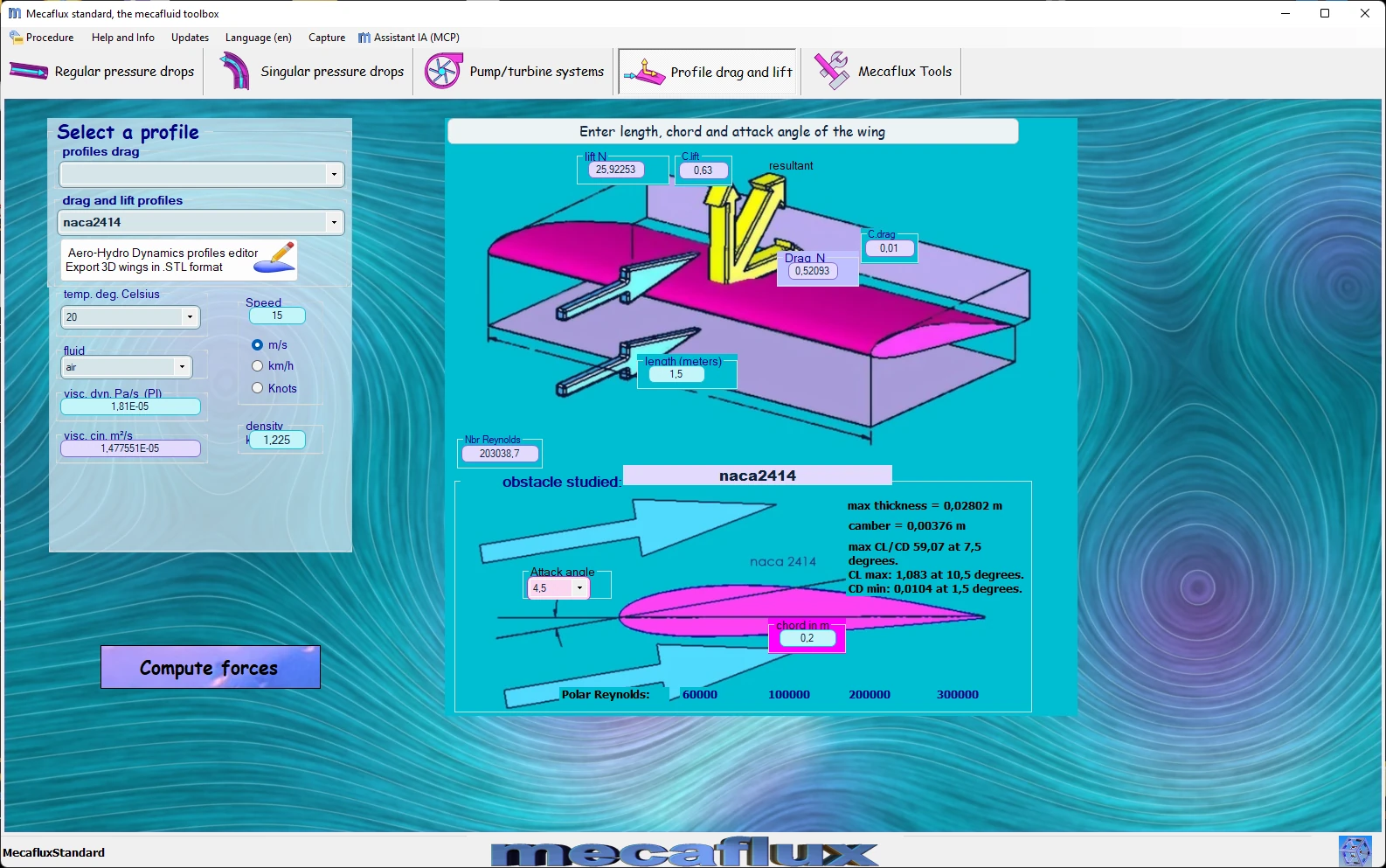
Frequently asked questions
Which reference area should I use to calculate drag?
Does the drag coefficient depend on the speed?
How can the drag of a body be reduced?
How do I calculate the drag of my own vehicle, hull or wing?